Table of Contents
Advertisement
Quick Links
Advertisement
Table of Contents

Subscribe to Our Youtube Channel
Related Manuals for Martin Audio WPL


Summary of Contents for Martin Audio WPL
- Page 1 Optimised Line Array User Guide...
-
Page 2: Table Of Contents
WPL Connections WPLGRIDt Touring Flying Frame Transport Cart for WPL Ground-stack Bar and Outriggers Inclinometer Assembly Flown Systems Rigging WPL with WPLGRIDt Landing the Array Ground-stack Deployment Specifications WPL Specifications WPL USER GUIDE V1.0 Copyright © 2019 Martin Audio Ltd. -
Page 3: Wavefront Precision Longbow
It is not however the intention for this manual to be the sole tutorial medium for those wishing to use the system. Extensive training media is available via the Martin Audio website and training webinars are held on a regular basis in order to help you gain a full understanding of the systems and their operation. -
Page 4: Important Safety Instructions
• Only use attachments / accessories specified by Martin Audio. • Use only with wheelboard and rigging hardware specified by Martin Audio. When moving using supplied wheelboards, caution should be used to avoid injury from the cabinet tipping over. •... -
Page 5: System Overview
Acoustic Design The WPL’s low frequency section consists of 2 x 12” (300mm) neodymium drivers in a Hybrid confi guration which marries the benefi ts of horn and refl ex loading. Each driver is slot-loaded into a short horn to give a high sensitivity of 103dB @ 1m/2.83V, while the rear of the driver is refl ex-loaded to extend the LF output. -
Page 6: Acessories
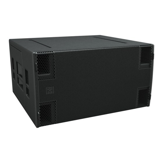
The SXH218 is an extremely powerful subwoofer capable of producing 148dB peak output at 1m. It is the ideal partner for Wavefront Precision WPL arrays where maximum low frequency output is required. It features dual long excursion 18” (460mm) /4.5” (115mm) voice coil neodymium driver with a water-resistant cone and triple roll surround in a Hybrid enclosure which couples the high effi ciency of a horn loaded system with the sub frequency extension of refl ex loading. -
Page 7: Display 2.3
DISPLAY opens with a dashboard at the top of the screen the initial view prompting you to specify your array which is the first step of the design process. WPL, WPC or WPM are available along with the Multicellular family of products. You next specify how your array will be deployed –... - Page 8 – and each region can be edited, perhaps changing a section under a balcony from audience to non-audience for example. The SPL profile can be modified and the environmental conditions entered to allow optimisation to compensate for air absorption, particularly critical for outdoor events. WPL USER GUIDE V1.0 Copyright © 2019 Martin Audio Ltd.
- Page 9 Hard Avoid performance. By default, each are given equal importance but if your application demands particular emphasis on any one of these parameters, they can be given greater importance. WPL USER GUIDE V1.0 Copyright © 2019 Martin Audio Ltd.
- Page 10 Wavefront Precision systems. DISPLAY 2.3 can be downloaded from the Martin Audio website: www.martin-audio.com/support/software. There is also a comprehensive user guide to take you through the design process in detail. We strongly recommend downloading the user guide to fully understand the application.
-
Page 11: Vu-Net 2.2
Overview VU-NET is Martin Audio’s application which is used to connect to iKON amplifiers and a growing number of products including the MLA family, CDD-LIVE!, PSX and DD12. This makes it possible to create a system with products from several different ranges and control and monitor them from a single software platform. - Page 12 The next stage is to right click on the amplifiers to access the ‘Preset Manager’. From here the system allows you up upload the D2P file of your system design. WPL USER GUIDE V1.0 Copyright © 2019 Martin Audio Ltd.
- Page 13 The output EQ is greyed out as it is used to apply the EQ created by your DISPLAY project, however the high-pass filter is available for adjustment so you can determine the crossover point between the WPL array and your subwoofers.
- Page 14 VU-NET is a free download from the software page of the Martin Audio website at www.martin-audio.com/support/software. It is a comprehensive application with a host of functions to enable control and monitoring of almost every parameter of a system. For full details we would strongly recommend downloading the VU-NET user guide which can be found on the same page as the application download.
-
Page 15: Rigging Wpl
Overview WPL’s three-point rigging system consists of two rigging points at the front and a single rigging point at the rear of the cabinet. The rear rigging bracket assembly (fi g. 3) provides eight rigging holes allowing for inter-cabinet angles of 0.5°, 1°, 2°, 3°, 4°, 5°, 6° and 7.5°, as well as STORE, LOCK, and LINK positions, for fl ying arrays or for use when assembling ground stacked arrays. -
Page 16: Wpl Connections
4 The two NL4s are wired in parallel so either can be used as a nominal ‘input’ or ‘link’ output. Since WPL is a bi-amped system all speaker cables and link cables must utilise 4-core cable. When the system is configured for a single box resolution system each cabinet is connected to two amplifier channels. -
Page 17: Wplgridt Touring Flying Frame
The touring flying frame is a comprehensively featured flying frame designed to meet BGVC1 and DIN18800 standards, and capable of lifting WPL using either one or two lift points up to a maximum of 24 WPL cabinets, (16 to meet BGVC1) allowing both positive (up-tilt) and negative (down-tilt) array tilt angles. -
Page 18: Transport Cart For Wpl
WPL USER GUIDE Transport Cart for WPL An optional, dedicated transport cart is available to house an array of four WPL cabinets. This will allow safe transportation and convenient rigging and de-rigging if your system is to be portable. fig. 7 fig. -
Page 19: Ground-Stack Bar And Outriggers
Ground-stack Bar and Outriggers This precision alignment bar (fig. 9) is used in conjunction with the touring flying frame to define the angle between the WPL array and the flying frame when the system is configured for ground stacking. Depending on where the ground-stack bar is attached to the touring flying frame, a range of aiming angles from +4°... -
Page 20: Inclinometer Assembly
Inclinometer Assembly Martin Audio supplies an optional remote angle monitoring system which can used to reliably check the angle at which the WPL array is flown (relative to the horizontal). It consists of a sensor (mounted within the flying frame) and a remote display unit. Interconnection is via a standard XLR mic cable. - Page 21 Note that the design of the box is such that the mounting and lid screws are positioned outside the lid gasket to ensure that there will be no moisture ingress through their holes. All screws are stainless steel to avoid corrosion when used outdoors (fig. 14). fig. 14 WPL USER GUIDE V1.0 Copyright © 2019 Martin Audio Ltd.
- Page 22 It can be connected to the read-out sensor with a standard 3-pin XLR mic cable of any length. Martin Audio supply a cable designed specifically for use with the inclinometer system, part number PWA00057. This is a 35m cable using high grade AES spec microphone cable fitted with male and female Neutrik NC3XX-HD connectors which are extra rugged and have an IP rating of IP67 to enable use outdoors in all weather conditions.
-
Page 23: Flown Systems
Flown Systems WPL uses a three-point rigging system. The mechanical load of the array is taken through the side-mounted steel rigging strips which securely connect one cabinet to the next, while the best possible coupling between cabinets is ensured by means of the rear rigging points which allow a range of angle adjustment from 0.5°... - Page 24 The front flying brackets are stored in the transit position and secured with rigging pins. Remove the pin on each side and raise the rigging bracket (fig. 19), then secure in the raised position by replacing the rigging pins (fig. 20). fig. 19 fig. 20 WPL USER GUIDE V1.0 Copyright © 2019 Martin Audio Ltd.
- Page 25 (fig. 22) determined by the holes in the rear bracket assembly, allowing inter-cabinet angle adjustment in eight incremental steps of 0.5°, 1°, 2°, 3°, 4°, 5°, 6° and 7.5°. fig. 21 fig. 22 WPL USER GUIDE V1.0 Copyright © 2019 Martin Audio Ltd.
-
Page 26: Rigging Wpl With Wplgridt
There are rubber pads on the underside of the top to hold the four cabinets securely when in transit. After removing the top of the transport cart and the supporting poles, the WPL array is easily accessible for rigging. Rigging pins are inserted at the holes required for the cabinet angles as predicted by your DISPLAY 2.3 project. - Page 27 WPL USER GUIDE Unlatch the top from the supporting poles in four places (fig. 27), lift it off and set it aside (fig 27). fig. 27 fig. 28 WPL USER GUIDE V1.0 Copyright © 2019 Martin Audio Ltd.
- Page 28 WPL USER GUIDE Unlatch the supporting poles (fig. 29) from the transport cart tray and lift them off (fig. 30). fig. 29 fig. 30 WPL USER GUIDE V1.0 Copyright © 2019 Martin Audio Ltd.
- Page 29 With the supporting poles removed from the transport cart the inter-cabinet angles should now be checked or, if not already preselected, set them now according to the predictions from your DISPLAY 2.3 project (fig. 31). fig. 31 WPL USER GUIDE V1.0 Copyright © 2019 Martin Audio Ltd.
- Page 30 WPL USER GUIDE Lift the front rigging brackets on the left and right of the top WPL in the cart (fig. 32) and pin in position (fig. 33). fig. 32 fig. 33 WPL USER GUIDE V1.0 Copyright © 2019 Martin Audio Ltd.
- Page 31 Most arrays will use the front rigging position, the rear position is required when the array has an excessive up-tilt. fig. 34 Insert a rigging pin at the front rigging position on each side (fig. 35). fig. 35 WPL USER GUIDE V1.0 Copyright © 2019 Martin Audio Ltd.
- Page 32 Attach the drop link from the rear of the top cabinet to the flying frame at the LINK position (fig. 36). fig. 36 Insert a rigging pin at the LOCK position (fig. 37). fig. 37 WPL USER GUIDE V1.0 Copyright © 2019 Martin Audio Ltd.
- Page 33 Cables are not shown for clarity. fig. 38 Support the rear of the cart and remove the rear pin holding the cart to the array (fig. 39). fig. 39 WPL USER GUIDE V1.0 Copyright © 2019 Martin Audio Ltd.
- Page 34 Lower the back of the cart to the ground (fig. 40). fig. 40 Repeat at the front of the array supporting the cart and removing the pins holding the cart to the array. fig. 41 WPL USER GUIDE V1.0 Copyright © 2019 Martin Audio Ltd.
- Page 35 Once the cart is removed the four supporting poles can be placed in the base (fig. 42) and the top fitted directly to the base and the two clipped together (fig. 43). The assembly can now be moved to a suitable location for storage. fig. 42 fig. 43 WPL USER GUIDE V1.0 Copyright © 2019 Martin Audio Ltd.
- Page 36 Lift the array to a height where a second cart can be placed underneath (fig. 44). fig. 44 Position a second loaded WPL transport cart underneath the array (fig. 45), remove the top and poles and prepare the cabinets to be added to the array.
- Page 37 WPL USER GUIDE Unlatch the top from the supporting poles in four places (fig. 46), lift it off and set it aside (fig. 47). fig. 46 fig. 47 WPL USER GUIDE V1.0 Copyright © 2019 Martin Audio Ltd.
- Page 38 WPL USER GUIDE Unlatch the supporting poles from the transport cart tray (fig. 48) and lift them off (fig. 49). fig. 48 fig. 49 WPL USER GUIDE V1.0 Copyright © 2019 Martin Audio Ltd.
- Page 39 Preselect the inter-cabinet angles on the lower three cabinets according to the predictions from your DISPLAY 2.3 project (fig. 50). fig. 50 Remove the rigging pins (fig. 51). fig. 51 WPL USER GUIDE V1.0 Copyright © 2019 Martin Audio Ltd.
- Page 40 5th cabinet Raise the front rigging brackets on the fifth cabinet and insert a rigging pin on both sides in the fourth cabinet (fig. 53). 4th cabinet fig. 53 5th cabinet WPL USER GUIDE V1.0 Copyright © 2019 Martin Audio Ltd.
- Page 41 WPL USER GUIDE Insert the front rigging pins into the fifth cabinet (fig. 54). 4th cabinet fig. 54 5th cabinet Lower the upper array (fig. 55). 4th cabinet fig. 55 5th cabinet WPL USER GUIDE V1.0 Copyright © 2019 Martin Audio Ltd.
- Page 42 Insert front rigging pins in the fifth cabinet (fig. 56). 4th cabinet fig. 56 5th cabinet Raise the array clear of the transport cart, allowing access to the rear of the array (fig. 57). fig. 57 WPL USER GUIDE V1.0 Copyright © 2019 Martin Audio Ltd.
- Page 43 Swing the bottom four cabinets (which will now be a rigid array due to the rigging pins) backwards until butted against the upper half of the array (fig. 59). fig. 59 WPL USER GUIDE V1.0 Copyright © 2019 Martin Audio Ltd.
- Page 44 LINK and LOCK positions on the fourth cabinet (fig. 60). Connect the cable loom and any link cables as required to the lower four cabinets. fig. 60 Support the rear of the cart and remove the rear pin holding the cart to the array (fig. 61). fig. 61 WPL USER GUIDE V1.0 Copyright © 2019 Martin Audio Ltd.
- Page 45 Lower the back of the cart to the ground (fig. 62). fig. 62 Repeat at the front of the array supporting the cart and removing the pins holding the cart to the array (fig. 63). fig. 63 WPL USER GUIDE V1.0 Copyright © 2019 Martin Audio Ltd.
- Page 46 (fig. 64 and 65). fig. 64 fig. 65 Stow the supporting poles in the tray of the transport cart, replace the top and secure the clips. fig. 66 WPL USER GUIDE V1.0 Copyright © 2019 Martin Audio Ltd.
-
Page 47: Landing The Array
WPL transport cart, unpinning the lower block of four, and repeating with the top four cabinets. Lower the array to a convenient working height. Disconnect the speaker cables. Position a WPL transport cart underneath the array and remove the top and supporting poles. - Page 48 WPL USER GUIDE At the back of the array raise the cart (fig. 69). fig. 69 Pin the cart to the rear rigging bracket of the array (fig. 70). fig. 70 WPL USER GUIDE V1.0 Copyright © 2019 Martin Audio Ltd.
- Page 49 Lower the array until the cart is on the ground taking the weight of the array allowing the cabinets to collapse down until the trapezoidal sides are touching (fig. 72). fig. 72 WPL USER GUIDE V1.0 Copyright © 2019 Martin Audio Ltd.
- Page 50 Carefully unpin the fifth cabinet from the fourth cabinet at the rear by removing the LINK pin (fig. 73), be aware that the array may swing when this is done. 4th cabinet fig. 73 5th cabinet Lower the array down so that the cart meets the floor (fig. 74). fig. 74 WPL USER GUIDE V1.0 Copyright © 2019 Martin Audio Ltd.
- Page 51 Remove the front rigging pins from the front of the fifth cabinet at each side (fig. 75). Ensure the cart is fully grounded when removing pins. 5th cabinet fig. 75 Lift the array a fraction so that there is no weight on the front rigging brackets (fig 76). fig. 76 WPL USER GUIDE V1.0 Copyright © 2019 Martin Audio Ltd.
- Page 52 WPL USER GUIDE Remove the front link pins (fig. 77). The front links will then drop down. fig. 77 Lift the remaining array cabinets away from the cart (fig. 78). fig. 78 WPL USER GUIDE V1.0 Copyright © 2019 Martin Audio Ltd.
- Page 53 WPL USER GUIDE Replace the front rigging pins in into the cabinet (fig. 79). fig. 79 Replace the supporting poles and top into the base of the WPL cart (fig. 80). fig. 80 WPL USER GUIDE V1.0 Copyright © 2019 Martin Audio Ltd.
- Page 54 WPL USER GUIDE Replace the lid of the WPL cart (fig. 81). fig. 81 Lower the remaining four cabinets and repeating the procedure above, lowering the array into a transport cart. WPL USER GUIDE V1.0 Copyright © 2019 Martin Audio Ltd.
-
Page 55: Ground-Stack Deployment
WPL USER GUIDE Ground-stack Deployment For ground stacking first find a suitable safe, flat surface and place the WPL flying frame in position. Remove the pins securing the front flip-up bars and swing the bars up until they are vertical (fig. 82). - Page 56 Replace the upper pin and add a second pin in the lower hole (fig. 84). Repeat for the other side. fig. 84 The grid is now ready for the ground-stack bar (fig. 85). fig. 85 WPL USER GUIDE V1.0 Copyright © 2019 Martin Audio Ltd.
- Page 57 Fit the ground-stack bar into the appropriate hole in the central spine of the flying frame (fig. 86). Note that the orientation of the bar and the correct hole to use in the frame will be determined by the angle of the first WPL cabinet in the stack and will be calculated by the DISPLAY 2.3 project.
- Page 58 WPL USER GUIDE Insert rigging pins in the WPL front brackets (fig. 88). fig. 88 Remove the rigging pins in the upper front rigging brackets and raise the linking bar (fig. 89). fig. 89 WPL USER GUIDE V1.0 Copyright © 2019 Martin Audio Ltd.
- Page 59 Replace the rigging pins to hold the bars in the up position (fig. 90). fig. 90 Raise the rear of the WPL which will hinge on the front pins. Swing the ground-stack bar up until the upper hole is aligned with the lowest hole on the WPL rear rigging bracket (fig. 91).
- Page 60 Insert a rigging pin in the lowest hole to secure the rear of the WPL (fig. 92). fig. 92 You now repeat the process for the second cabinet, removing the front pins and lowering it onto the first WPL (fig. 93). 2nd cabinet fig.
- Page 61 Lift the back of the second cabinet until the angle is reached and insert a rigging pin in the LOCK position to hold the cabinet at the required angle (fig. 95). fig. 95 WPL USER GUIDE V1.0 Copyright © 2019 Martin Audio Ltd.
- Page 62 WPL USER GUIDE Repeat the process adding cabinets to build the ground-stack to the required number of WPL (fig. 96). fig. 96 WPL USER GUIDE V1.0 Copyright © 2019 Martin Audio Ltd.
-
Page 63: Specifications
WPLOUTRIG – Ground-stacking accessories IK42AMPRACK-UK+ – Fully populated amplifi er rack (Euro) K42AMPRACK-US+ – Fully populated amplifi er rack (US) WPLCART – Transport cart ASM20017 – Inclinometer sensor ASM20019 – Inclinometer reader WPL USER GUIDE V1.0 Copyright © 2019 Martin Audio Ltd. - Page 64 All information is Copyright © 2019 Martin Audio Ltd. Martin Audio, the Martin Audio logo and Hybrid are registered trademarks of Martin Audio Ltd. in the United Kingdom, United States and other countries; all other Martin Audio trademarks are the property of Martin Audio Ltd.
Need help?
Do you have a question about the WPL and is the answer not in the manual?
Questions and answers
How to ground stack