
Related Manuals for Oliver 4470


Summary of Contents for Oliver 4470
- Page 1 4470 Industrial Planer 25” Owner’s Manual Oliver Machinery M-4470 9/2017 Kent, WA 98032 © Copyright 2003 info@olivermachinery.net www.olivermachinery.net...
-
Page 3: Warranty
Oliver makes every effort possible to assure that its equipment meets the highest possible standards of quality and durability. All products sold by Oliver are warranted to the original customer to be free from defects for a period of 2 (two) years on all parts, excluding electronics and motors, which are warranted for 1 year. -
Page 4: Segmented Infeed Roller Diameter (In.)
WARNING Read this manual completely and observe all warning labels on the machine. Oliver Machinery has made every attempt to provide a safe, reliable, easy-to-use piece of machinery. Safety, however, is ultimately the responsibility of the individual machine operator. As with any piece of machinery, the operator must exercise caution, patience, and common sense to safely run the machine. -
Page 5: Number Of Knives
15. Do not use this Oliver planer for other than its intended use. If used for other purposes, Oliver disclaims any real or implied warranty and holds itself harmless for any injury or damage which may result from that use. -
Page 6: Table Of Contents
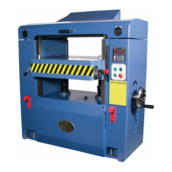
Adjusting Table Rollers..........................16 Maintenance..............................16 Lubrication..............................17 Troubleshooting............................18 Specifications Stock No..................(10HP, 1Ph HSS Straight Knife) 4470.001 Stock No..................(15HP, 3Ph HSS Straight Knife) 4470.002 Stock No.................(10HP, 1Ph Carbide Helical Cutterhead) 4470.101 Stock No.................(15HP, 3Ph Carbide Helical Cutterhead) 4470.102 Maximum Stock Width (in.)........................25 Maximum Depth of Cut (in.)........................1/4 Maximum Stock Thickness (in.)......................9-1/4... -
Page 7: Warnings
Oliver 4470 - 25” Industrial Planer 1. 25” Planer Box 1 4. Leveling Pads 3. Hex Key Wrenches 3. Open End Wrenches 1. Screwdriver 2. Knife Setting Gauges 1. Knife Setting Gauge Shaft 4. E-Clips 1. Handle Box 2 1. Dust Chute 8. -
Page 8: Electrical Connections
Electrical Connections WARNING! Electrical connections and wiring must be done by a qualified electrician. The machine must be properly grounded. Failure to comply may cause serious injury! This planer is available in both 1-Phase and 3- Phase versions. • Electrical Connections for a 3-Phase Unit This planer is 3-Phase, 220V/440V pre-wired 220V. -
Page 9: Assembly
Dust Chute Assembly N. The “Set” button is used when calibrating or setting the thickness scale. Mount the dust chute (A, Figure 2) to the planer hood with eight M6x10 hex head screws (B, Figure 2). Make sure the dust collection system has sufficient capacity and suction for your planer. -
Page 10: Changing Units Of Measure
Changing Units of Measure Press unit button (A, Figure 5) to toggle back and forth between inches and millimeters. Calibrating the Display The following sections will describe the use of a calibrating board. The calibrating board should be made of a hardwood and have one side that has been run through a jointer. -
Page 11: Raising And Lowering Table
Raising and Lowering Table Turn the handwheel (A, Figure 7) clockwise to raise the table. One revolution equals 1/32” or 0.03”. Note: The handwheel is spring loaded. Push in on the handwheel and rotate until the pins engage the detents. Adjusting Thickness Scale 1. -
Page 12: Setting / Changing Knives
Knives are extremely sharp. Be very careful when handling knives. Failure to comply may cause serious injury! The Oliver 25” planer was designed to accept 25-1/8” x 1” x 1/8”) knives. Installing straight knives accurately is an important step to achieve a smooth finish. -
Page 13: Setup Of Feed Rollers, Chipbreaker And Pressure Bar
Setup of Feed Rollers, Chipbreaker and Pressure Bar WARNING! Disconnect machine from the power source before performing any adjustments or maintenance. Failure to comply may cause serious injury! The planer comes set up from the factory and shouldn’t need any adjustment. If you find adjustment is necessary, follow the below listed sections for setting the in-feed roller, chipbreaker, pressure bar and outfeed rollers. -
Page 14: Anti-Kickback Fingers
Anti-Kickback Fingers Anti-kickback fingers help prevent stock from being kicked out of the machine towards the user. Keep the fingers clean and free from sawdust, pitch gum, etc. so they operate smoothly. Adjustment of In-Feed Roller The in-feed roller should be set 0.02” below the lowest point of knife. -
Page 15: Adjustment Of Pressure Bar
Adjustment of Pressure Bar The pressure bar should be set even with the lowest point of knife. Make sure the knives are set properly see the “Setting / Changing Knives” section on page 11 prior to making any adjustments. 1. Disconnect machine from power source. 2. -
Page 16: Helical Cutterhead
Helical Cutterhead WARNING! Knives are extremely sharp. Be very careful when handling knives. Failure to comply may cause serious injury! The helical cutterhead is set-up with the same relationship to the in-feed roller, chipbreaker, pressure bar and outfeed rollers as the straight knife cutterhead. -
Page 17: Adjusting Table Rollers
Adjusting Table Rollers The table rollers come pre-set from the factory and shouldn’t need any adjustment. If you find adjustment is necessary, follow the below listed steps. 1. Lay a straight edge (A, Figure 23) on the table across the roller (B, Figure 23). 2. -
Page 18: Lubrication
Lubrication • Add a few drops of medium weight oil to the six oil cups (A, Figure 25) weekly or every eight hours of use (which ever comes first). • Lubricate the two table elevation screws (B, Figure 26) as needed. Raise the table and remove the two screws holding the top of the accordion cover (C, Figure 26) in place. -
Page 20: Troubleshooting
Halted Feeding If the in-feed roll takes stock away from you while feeding, then feeding stops before contacting the knives, the chipbreaker is probably too low. Or the in-feed roller is not set low enough, or does not have enough pressure. In a similar situation, the in-feed roll takes the stock, the chipbreakers lift, and stops as you hear the knives contact the material. - Page 21 Controller (M15S) Operating Instructions 1. Front Panel Overview M15S minikol ● Target value window ● ● ● ● ● ● ● Real value window ● ● ● ● ● ● ● ● ● Manual Single PEOG INCH START ● STOP...
- Page 22 2. Operation Modes There are two base operating modes – MANUAL and SINGLE In MANUAL mode, the operator can raise or lower the table using the Controller keypad. In SINGLE mode, the table will move to the pre-set value when you push the “Table Up”...
- Page 23 For planer table operations, the fast forward and fast backward keys have the same function as the forward and backward keys. When the forward key is pressed, the planer table moves down. (This is also achieved using the “Table Down” push button on the planer). When the back ward key is pressed, the planer table moves up.
- Page 24 Start/Stop/Cancel Press to start the positioning. The LED lamp now stops blinking and START remains on during the procedure. Press to cancel the positioning. The LED lamp is turned off. STOP If the key is pressed while the positioning is running, the procedure is STOP interrupted, the machine is stopped, and the LED is turned off.
- Page 25 Target value on display = 100.00 mm Read value on display = 100.00 mm To change the target value to 20.25 mm, Step 1: Press , the LED lamp on Target window is blinking. PROG 100.00 Target value Display 100.00 Current value Step 2: Enter new target value (example: 20.25 mm) Press...
-
Page 26: Maximum Stock Width (In.)
3. Fast program (10 sets) To facilitate frequently used positions, such as different board thicknesses, the keys 0 to 9 have associated preset target values. By pressing one of these keys, its target value is loaded automatically, and the positioning can be started immediately. - Page 27 Step 2: Press …………………….………………[select program key 0] Step 3: Press ………………………..…[enter value] Step 4: Press …………………………………………………[complete] Step 5: Press …………………………………….[select program key 1] Step 6: Press ……………………...……[enter value] Step 7: Press ……………………………………...…………[complete] Step 8: Press to exit. Execute: MANUAL Step 1: Enter single mode, LED lamp is off.
- Page 28 Step 2: Press a key 0 to 9 LED lamp is blinking, ready for start. START Example: Program 0 = 10:00 mm; Program 1 = 20.00 mm. MANUAL Step 1: In Single Mode, LED lamp is off. SINGLE Step 2: Press ……………………………………...……….[Program 0] Now you will see the preset value: 10.00 mm [Program 0] START...
- Page 29 4. Select Counting Direction You can select the counting direction according to the table movement. Step 1: Press — Display …[default] Step 2: Press to change the direction. PROG “ – dir ” numbers decrease as table rises (accords with scale on planer). “...
- Page 30 Step 3: Press to confirm or press to clear. 6. Set Software Limit (Hi/Lo End) There are High and Low software limits. If there are exceeded, the display will give an error message. Te set the Lo_End press Te set the Hi_End press 7.
- Page 31 8. Set Low Speed Limit This function defines the speed level which is considered abnormal for the machine. When the Controller starts the table movement up or down, and the table does not move, or moves with a speed lower than defined, it stops the machine and displays. E n G i n E F A u l t Press...
- Page 32 Step 3: Press to confirm or press to clear. 9. Set Linear Correction Step 1: Press l i n C o r Display 1.00000 Step 2: Enter the value between 0.0001 and 9.999 Step 3: Press to confirm or press to clear.
- Page 33 10. Enter Parameter Settings Mode With this function, you can select each parameter to be locked or unlocked. When a parameter is locked, then the end-user can only see the value, but can not change it. Step 1: Press P A S S Display _ _ _ _ Step 2: Enter the password.
- Page 34 11. Check Software Version To check the released version of the M15S Controller program: Step 1: Press S o u r C E Display A C – 1.00 In the real value window, you will see the released version. Step 2: Press to confirm or press to clear.
- Page 35 Load the real value: C H A n G E Display O r G ? ? Step 1: Press to confirm or press to cancel. Example: The current value is 10.00 mm but the actual thickness is 10.50 mm. Step 1: Press O r i G i n Display 0.00...
- Page 36 Step 4: Press 13. IN/MM Conversion The dedicated mm/inch key allows for immediate switch of the units between millimeters and inches. The LEDs on the key indicate the selected unit. Switching between MM and INCHES has no effect on the control functions. When this LED lamp twinkles –...
- Page 37 15. Calibration Step 1: Press G o ● ● ● ● Display Step 2: Use to move the planer table until M15S terminates the calibration and restarts. 16. M15S Troubleshooting C H A n G E Display r S t “Change RST”...
- Page 38 Check the wiring and change if necessary. S E n S o r Display E r r o r Possible cause: a. no sensor b. 9-pin connector is loose c. Wire broken d. The gap between sensor and tape is too large Excluding: Check the sensor, sensor cable and sensor connector.
-
Page 39: Specifications
17. M15S Specifications Feature Technical Data Additional Information Supply voltage 24 VDC 50Ma C type battery x 1 Battery voltage control Low power alarm via display Display 15mm LED x 6 digits x 2 line AC250V / 7A Output 4 digital output AC110V/7A DC24V/10A Input... - Page 41 Oliver 4470 25" Planer Index Old Part Part Number Item Descriptions Specfications Number 850245-000 Bagged Hardware PQ0201 29 250054-615 Handle Knob LJ010110 30 360414-910 Handle Shaft PN010025 99 041305-003 Poly Bag 275*185*0.1t HR043800 131 040003-000 Hex. Wrench HQ010400 159 040004-000 Hex.
- Page 42 050580-000 Left Column PQ010022 921333-000 Idle Belt Pulley Set .1 008308-100 Nylon Nut M10*1.5P(17B*12H) HC041000 .2 171709-902 Idle Belt Pulley Bracket .3 006001-069 Flat Washer 10*20*3.0t HE019400 .4 010101-000 R-Ring RTW-30 HF022800 .5 030105-000 Ball Bearing 6200ZZ HJ021800 .6 380458-902 Idle Belt Pulley .7 000803-102 Round HD Socket Bolt...
- Page 43 000204-102 SET Screw M8*1.25P*10 14 HA030504 006712-100 Wavy Washer BWW-6001 HE071500 006001-056 Flat Washer 8.5*23*2.0 HE015300 050881-000 Cutterhead Bracket (Left) 360624-902 Fixed Shaft 360151-902 360629-902 Press Shaft PP010024 010011-000 S-Ring STW-25 HF012300 380470-902 Front Roller Spacer 190075-902 012005-006 8*7*16 HH010709 360506-000 Front Roller Shaft PQ020004...
- Page 44 .11 012003-002 5*5*10 HH010405 .12 043605-000 Oil Seal TC24*40*7 HM142103 .13 030208-000 Ball Bearing 6204-2NSE HJ032200 .14 320208-000 Gear (20T) PN010302 .15 010007-000 S-Ring STW-16 HF011400 .16 030205-000 Ball Bearing 6201-2NSE HJ031900 .17 043603-000 Oil Seal TC20*40*7 HM140803 .18 010011-000 S-Ring STW-25 HF012300...
- Page 45 124 360636-902 Crank PP010057 125 000202-102 SET Screw M5*0.8P*8 HA030303 126 130048-903 Block PN010044 127 290016-901 Shoulder Screw (B) PN010075 128 170900-902 Transmission Link PP010055 129 012003-002 5*5*10 HH010405 130 010501-000 ISTW-Ring ISTW-30 HF090100 132 171396-156 Indicator Bracket PQ010018 133 170899-902 Transmission Link PP010054 134 360420-902...
- Page 46 174 360643-000 Gear Shaft PP010079 175 012003-007 5*5*20 HH010411 176 320208-000 Gear (20T) PN010302 177 006001-103 Flat Washer 16.8*38*2.5t HE017500 178 016009-000 Chain #40*58P HK244600 179 150014-000 Chain Gear (B) PN010309 180 920372-000 Hand Wheel Ass'y PP0102 .1 230046-000 Fold Handle PP010029 .2 000702-102 Flat HD Socket Bolt...
- Page 47 217 014107-000 V-Belt HK024300 218 070017-000 Chain Gear (26T) PN010018 219 280067-901 Spring TJ010013 220 170897-000 Rear Base Cover PP010047 221 021802-000 Cord Ring NB-2430 HP200200 222 021805-000 Cord Ring NB-1216 HP200500 223 170894-000 Cord Plate PP010037 224 008308-100 Nylon Nut M10*1.5P(17B*12H) HC041000 225 170638-156...
- Page 48 269 520001-249 Carboard Box for Parts 680*170*440 PN010090 270 520001-221 Carboard Box for Dust Hood 370*250*110 PG071101 271 041503-019 Plastic Board 920*710*0.05t 630019-000 272 640020-000 Anti-Rust Bag 1800*2400*0.1t EQ010060 273 610003-025 Closed Plywood Box 1350*880*1520 PP010031 *274 PQ02-10 Label PQ1A 282 041305-018 Poly Bag 600*540*0.1t...
Need help?
Do you have a question about the 4470 and is the answer not in the manual?
Questions and answers