Table of Contents
Advertisement
Advertisement
Table of Contents

Related Manuals for Reichert Model 30


Summary of Contents for Reichert Model 30
- Page 1 Model 30 ™ Pneumatonometer User’s Guide...
- Page 2 The information contained in this document was accurate at time of publication. Specifications subject to change without notice. Reichert, Inc. reserves the right to make changes in the product described in this manual without notice and without incorporating those changes in any products already sold.
-
Page 3: Table Of Contents
Contents Warnings and Cautions ................... 4 Symbol Information ..................6 Introduction ...................... 7 Indications for Use ..................7 Contraindications ..................7 Instrument Setup ....................8 Unpacking Instructions ................8 Parts Identification ..................9 Models and Options ................10 Accessories ..................10 Icon Definition .................. -
Page 4: Warnings And Cautions
Warnings & Cautions Reichert Technologies is not responsible for the safety and reliability of this instrument when: • Assembly, disassembly, repair, or modification is made by unauthorized dealers or persons. • Instrument is not used in accordance with this User’s Guide. - Page 5 CAUTION: THIS INSTRUMENT IS NOT INTENDED TO BE CONNECTED TO EQUIPMENT OUTSIDE THE CONTROL OF REICHERT INC. OR MUST BE TESTED TO AN APPLICABLE IEC OR ISO STANDARDS. CAUTION: DO NOT INSTALL ANY ADDITIONAL SOFTWARE OTHER THAN WHAT WAS SUPPLIED WITH THIS INSTRUMENT.
-
Page 6: Symbol Information
Symbol Information Symbol Information The following symbols appear on the instrument: Caution Type B Applied Part Alternating Current Power Protective Earth Connection ON / OFF Manufacturer Date of Manufacture 2017 Catalog Number Serial Number Waste of Electrical and Electronic Equipment Compliance to Medical Device Directive 93/42/EEC Authorized to mark given by Intertek ETL Semko for conformance with electrical standards... -
Page 7: Introduction
Indications for use The Model 30 Classic Pneumatonometer is intended for the measurement of intraocular pressure. The Model 30 Classic Pneumatonometer is indicated for use as a screening / monitoring tool for glaucoma or when increased intraocular pressure is suspected. -
Page 8: Instrument Setup
Instrument Setup Great care has been taken to deliver this instrument to you safely. The container and packaging was specially designed to transport this unit. Please retain the packaging if future transportation is required. Please remove the packaging material from the outer box and then remove the pneumatonometer and its accessories from the box. -
Page 9: Parts Identification
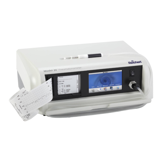
Parts Identification The Model 30 Pneumatonometer is housed in a single compact metal case that fits easily on most coun- ters or an appropriate stand. The front panel of the Model 30 Pneumatonometer includes: (Refer to the Figure 1-4.) 1. -
Page 10: Models And Options
The tonography test enables the operator to conduct a two-minute or four-minute test for each eye. The Model 30 Pneumatonometer handpiece and probe assembly (Figure 1-6) includes: 1. Tip and membrane assembly (Applied Part) 2. -
Page 11: Icon Definition
Instrument Setup continued) Icon Definition The Pneumatonometer incorporates a user-friendly icon/menu-based operating system that will increase the speed of measurements, training and use. Below are the Icons that are used during the operation of this instrument. Icon Icon Description Access the setup menu for changing default pa- SETUP rameters. - Page 12 Instrument Setup continued) Icon Definition (continued) Icon Icon Description RETURN Returns to preceding screen. RIGHT ARROW Used in the setup menus to move right horizontally. LEFT ARROW Used in the setup menus to move left horizontally. UP ARROW Used in the setup menus to move up vertically. DOWN ARROW Used in the setup menus to move down vertically.
-
Page 13: Default Settings
Instrument Setup continued) Default Settings This instrument is sent from the factory with measurement, chart, and other general parameters assigned to default settings. These settings can be changed to the preferences of the operator/clinician. A summary of these settings is given below. The optional settings follow on subsequent pages. General Setup: Chart: Footswitch: Off... -
Page 14: Printout Setup
This sample screen provides the details of the Software Version, Calibration Date, and the customer service telephone number. If assistance is needed with this unit, consult the Troubleshooting section of this manual. If further assistance is needed, please contact the customer service department at Reichert, Inc. 16030-101 Rev. J... -
Page 15: Installation
Instrument Setup continued) Installation Consider the following factors as you find a location for the Model 30 Pneumatonometer: • When taking tonometry measurements with the pneumatonometer, the patient can be either seated or supine. When conducting tonography tests, the patient must be supine. - Page 16 Instrument Setup continued) Pneumatonometer Installation (continued) 4. Remove the probe from its container and place the clean tip and membrane assembly that was sent with the unit onto the probe, if one is not already installed. If a tip is not installed, perform the fol- lowing: A.
-
Page 17: Application Of Input Power
Instrument Setup continued) Application of Input Power This section describes the Model 30 Pneumatonometer initialization. 1. Turn the instrument ON by pressing down the “I” on the front panel ON /OFF switch. At start-up, the Model 30 Pneumatonometer LCD readout will display the initial screen for several seconds as the instrument conducts a self-check test. -
Page 18: Disconnection Of Input Power
Instrument Setup continued) Application of Input Power (continued) 5. Touch the DOWN ARROW icon to highlight the Printout Setup option. 6. Touch the OK icon to select the Printout Setup menu. Refer to Figure 2-4. 7. Touch the UP or DOWN icons to highlight the option that needs to be changed and touch the OK icon to select the option. -
Page 19: Quick Verification Check
Note: If the IOP is not 15 mmHg (± 2.0 mmHg), go to the Troubleshooting section of this manual for assistance. If the Troubleshooting section of the manual did not help, contact Reichert at the address or phone number in the Introduction section of this manual. -
Page 20: Operating Principle
A precisely regulated flow of filtered air enters the piston from the Model 30 Pneumatonometer and travels through the end of the sensor tip until it is blocked by the membrane. When nothing is touching the mem- brane, air flows to the periphery of the tip, where it escapes through venting ports. -
Page 21: Instructions For Use
In pulse tonometry mode, the ocular pulse waveform is charted and recorded along with IOP. There are three different tests that can be performed with the Model 30 Pneumatonometer. They are: Manual Tonometry... -
Page 22: Measurement Protocol
Instructions for Use continued) Measurement Protocol CAUTION: THE TIP AND MEMBRANE ASSEMBLY MUST ALWAYS BE CLEANED BEFORE AND AFTER MEASUREMENTS. REFER TO THE REPROCESSING SECTION OF THIS MANUAL FOR THE SUGGEST- ED CLEANING INSTRUCTIONS. 1. From the main menu screen, select the Manual, Pulse, or Tonography test as necessary. -
Page 23: Measurements
Instructions for Use continued) Measurements Manual Tonometry To measure IOP using the manual tonometry mode, follow this procedure: Note: If a graphical output is desired, go to the Setup menu and set the printer to ON. 1. Touch the MANUAL IOP icon and then touch the OS or the OD icon. -
Page 24: Pulse Tonometry
Measurement Protocol Figure 6-1, Main Menu Screen paragraph in this section. Refer to Figure 6-3. Note: The tone will change when the Model 30 Pneumatonometer has sensed five ocular pulses indicating that the instrument has enough samples to compute an average. The instrument will end the test after it has sensed ten ocular pulses. -
Page 25: Tonography
(continued) Tonography The tonography test measures aqueous humor outflow. In this test, the Model 30 Pneumatonome- ter records changes in IOP when a weighted probe is held on the cornea for a specified time. The pneumatonometer enables the operator to conduct a two-minute or four-minute test for each eye. -
Page 26: Seated Iop
Figure 7-7, Changing IOP Note: If the probe loses contact with the eye before the end of the test, the Model 30 Pneuma- tonometer will abort the test. The instrument will then give a prompt to choose between START TONOGRAPHY and CALCULATOR MODE, that is, start the tonography portion of the test again or enter values manually from the measurements. - Page 27 Instructions for Use continued) Measurements (continued) Tonography (continued) Supine IOP (continued) 3. Touch either the Calculator or the Tonography icon to acquire the tonography data. Refer to Figure 7-8. • If the Tonography icon was selected, gently apply the probe with the 10 gram weight to the patient’s cornea and acquire the data until the tonography test ends.
-
Page 28: Cleaning & Maintenance
It is recommended by the manufacturer of the Model 30 Pneumatonometer to utilize the following process to achieve a high level of disinfection on the tip and membrane assembly. -
Page 29: Fuses
Cleaning & Maintenance continued) Fuses Fuses are located next to the power inlet. Replace fuses with only a rating as indicated on the power inlet panel. Refer to the Gen- eral Specifications section in this manual. Refer to Figure 8-1. WARNING: DISCONNECT POWER BEFORE ATTEMPTING TO REMOVE THE FUSES OR SERIOUS INJURY OR DEATH MAY OCCUR. -
Page 30: Printer Paper
CAUTION: TAKE CARE TO AVOID KINKING THE TUBING WHEN INSTALLING THE NEW FILTER INTO THE ACCESS CAVITY. 3. Replace the filter with the new filter from the Reichert Filter Kit (refer to the Accessories section of this manual for the P/N). Refer to Figure 8-6. -
Page 31: Troubleshooting
Troubleshooting The following chart provides details of common problems and solutions for the Model 30 Pneumatonometer. Definition Probable Cause Solution Screen is blank. ON/OFF Switch set to OFF. Press the “—“ on the ON/OFF Switch. Fuse(s) Blown. Replace blown fuse(s). -
Page 32: Specifications
Specifications This section contains the specifications for the Model 30 Pneumatonometer. Physical Dimensions Instrument Console Size: Weight, unpacked: 10.0 lbs. (4.54 Kg) Height: 5.25 in. (13.3 cm) Width: 14.0 in. (35.6 cm) Depth: 10.5 in. (26.7 cm) Instrument Probe Weight, unpacked: 2.0 ounces (57 grams) Size: Outside Diameter: 0.5 in. -
Page 33: Classifications
The Model 30 Pneumatonometer is classified as IPX0 Equipment. IPX0 Equipment is ordinary equipment enclosed without protection against ingress of water. According to the mode of operation, the Model 30 Pneumatonometer is a Continuous Operation instrument. 16030-101 Rev. J... -
Page 34: Guidance & Manufacturer's Declarations
Guidance and Manufacturer’s Declaration – Electromagnetic Emissions The Model 30 is intended for use in the electromagnetic environment specified below. The customer or user of the Model 30 should ensure that it is used in such an environment. Electromagnetic Environment... - Page 35 Guidance and Manufacturer’s Declaration – Electromagnetic Immunity The Model 30 is suitable for use in electromagnetic environment specified below. The customer or user of the Model 30 should ensure that it is used in such an environment. Immunity IEC 60601...
- Page 36 Guidance and Manufacturer’s Declaration – Electromagnetic Immunity The Model 30 is intended for use in the electromagnetic environment specified below. The customer or user of the Model 30 should ensure that it is used in such an environment. Immunity IEC 60601...
- Page 37 The Model 30 is intended for use in the electromagnetic environment in which radiated RF disturbances are controlled. The customer or user of the Model 30 can help prevent electromagnetic interference by maintaining a minimum distance between portable and mobile RF Communications Equipment and the Model 30 as recommended below, according to the maximum output power of the communications equipment.
- Page 38 Immunity to Proximity Fields from RF Wireless Communications Equipment Guidance and Manufacturer’s Declaration - Electronic Immunity The Model 30 is intended for use in the electromagnetic environment as specified below related to proximity fields from RF wireless communications equipment. Electromagnetic...
-
Page 39: Warranty
U.S. Patent, Reichert will defend such action at its expense and will pay costs and damages awarded in any such action, provided that Reichert shall have sole control of the defense of any such action with information and assistance (at Reichert’s expense) for such defense, and of all negotiation for the settlement and compromise thereof. - Page 40 Depew, NY 14043 Toll Free: 888-849-8955 Phone: 716-686-4500 Fax: 716-686-4555 Email: reichert.information@ametek.com www.reichert.com Authorized European Representative AMETEK GmbH Business Unit Reichert Carl-von-Linde-Strasse 42 85716 Unterschleissheim/Munich Germany Email: info.reichert-de@ametek.com Tel: +49 (89) 315 8911 0 Fax: +49 (89) 315 891 99 ISO-9001/13485 Certified 16030-101 Rev.J...
Need help?
Do you have a question about the Model 30 and is the answer not in the manual?
Questions and answers