Table of Contents
Advertisement
Quick Links
Advertisement
Table of Contents

Related Manuals for Carl Valentin PICA II


Summary of Contents for Carl Valentin PICA II
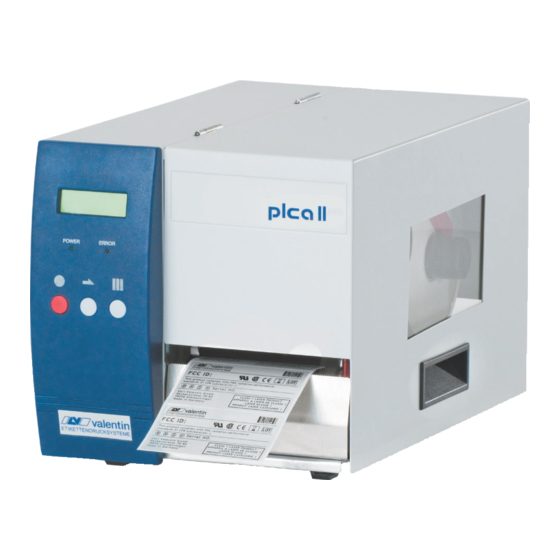
- Page 1 PICA II Service Instructions...
- Page 2 It must not be concluded from the missing labelling that it is not a registered brand or a registered trademark. Carl Valentin label printers comply with the following safety guidelines: EG Low-Voltage Directive (2006/95/EC) EG Electromagnetic Compatibility Directive (2004/108/EC)
-
Page 3: Table Of Contents
Pica II Table of Contents Table of Contents Table of Contents ................3 Notes on this Document ............5 User Notes ................5 Instructions ................5 Cross References ..............6 Safety Instructions ..............7 General Safety Instructions ............. 7 Safety Handling when Working with Electricity ....... 9 Connector Pin Assignment (Printer Rear) ...... -
Page 5: Notes On This Document
Pica II Notes on this Document Notes on this Document 1.1 User Notes This service manual is intended for qualified service and maintenance staff. This manual contains information about hardware and mechanical part of the label printers 104/8, 106/12, 103/8 T and 108/12 T. -
Page 6: Cross References
Notes on this Document Pica II 1.3 Cross References Item numbers References to specific items in a figure are marked with item numbers. They are identified with parentheses in the text, e.g. (9). If no figure number is provided, item numbers in the text always refer to the graphic directly above the text. -
Page 7: Safety Instructions
Pica II Safety Instructions Safety Instructions 2.1 General Safety Instructions ⇒ Workplace and Keep the area around the device clean during and after method of working maintenance. ⇒ Work in a safety-conscious manner. ⇒ Store dismantled device parts in a safe place while maintenance is being performed. - Page 8 Safety Instructions Pica II Protective clothing If a possible danger to your eyes is present, wear protective goggles, especially in the following cases: • when knocking in or knocking out pins and similar parts with a hammer • when using spring hooks •...
-
Page 9: Safety Handling When Working With Electricity
Pica II Safety Instructions 2.2 Safety Handling when Working with Electricity ⇒ Qualifications of The following work may only be performed by instructed and personnel trained electricians: work on the electrical assemblies work on the device while it is open and connected to the power supply. -
Page 10: Connector Pin Assignment (Printer Rear)
CAUTION! The label printer can be damaged by non-compliant winders. ⇒ Attach only winders of Carl Valentin. Serial Interface RS-232 Pin 2 = TXD, Pin 3 = RXD, Pin 5 = GND, Pin 7 = CTS, Pin 8 = RTS... -
Page 11: Cleaning
Pica II Cleaning Cleaning DANGER! Risk of death via electric shock! ⇒ Before opening the housing cover, disconnect the device from the mains supply and wait approx. 2 - 3 minutes until the power supply unit has discharged. Cleaning schedule... -
Page 12: Cleaning The Transfer Ribbon Drawing Roller
Cleaning Pica II 4.2 Cleaning the Transfer Ribbon Drawing Roller A soiled print roll can lead to reduced print quality and can affect transport of material. 1. Open printer cover. 2. Remove transfer ribbon from the label printer. 3. Remove deposits with roller cleaner and a soft cloth. -
Page 13: Cleaning The Printhead
Pica II Cleaning 4.4 Cleaning the Printhead Printing can cause accumulation of dirt at printhead e.g. by colour particles of transfer ribbon, and therefore it is necessary to clean the printhead in regular periods depending on operating hours, environmental effects such as dust etc. -
Page 14: Cleaning The Label Photocell
Cleaning Pica II 4.5 Cleaning the Label Photocell CAUTION! Label photocell can be damaged! ⇒ Do not use sharp or hard objects or solvents to clean the label photocell. The label photocell can become dirtied with paper dust and this can adversely affect label detection. -
Page 15: Replacing Components
Pica II Replacing Components Replacing Components DANGER! Risk of death via electric shock! ⇒ Before opening the housing cover, disconnect the device from the mains supply and wait approx. 2 - 3 minutes until the power supply unit has discharged. -
Page 16: Replacing The Printhead
Replacing Components Pica II 5.2 Replacing the Printhead NOTICE! The printhead (D) is preinstalled on a head plate (A) and aligned at the factory. Figure 5 Head plate Plug connection signal Plug connection tension Printhead Focal line Guiding Screw CAUTION! - Page 17 Pica II Replacing Components Figure 6 Removing the 1. Remove labels and transfer ribbon from the label printer. printhead 2. When printhead is closed, loosen the fixing screw (B). 3. Turn red lever (D) counter clockwise to lift up the printhead.
-
Page 18: Adjusting The Print Position
Replacing Components Pica II 5.3 Adjusting the Print Position Zero point adjustment NOTICE! in Y direction The value for zero point adjustment is set ex works. After replacing the printhead, only service personnel are allowed to set this value anew. -
Page 19: Replacing The Pressure Roller
Pica II Replacing Components 5.4 Replacing the Pressure Roller Figure 7 Removing the 1. Remove left printer cover. pressure roller Loosen two screws at the lower left printer edge and three screws at the chassis upper edge. 2. Remove the protective conductor at the inside of the printer cover. -
Page 20: Replacing The Label Photocell
Replacing Components Pica II 5.5 Replacing the Label Photocell NOTICE! Soiling of the label photocell can also cause malfunctions. Before replacing the label photocell, check whether it is soiled and clean it if necessary (see chapter 4.5, on page 14). -
Page 21: Replacing The Cpu Pcb
Pica II Replacing Components 5.6 Replacing the CPU PCB Figure 9 Removing the 1. Unplug the printer from the electrical outlet. CPU PCB 2. Detach all interface cables from the back of the printer. 3. Screw off the left printer cover. -
Page 22: Replacing The Power Supply
Replacing Components Pica II 5.7 Replacing the Power Supply Figure 10 Removing the 1. Unplug the printer from the electrical outlet. power supply 2. Remove the inside and outside label support as well as the label material (if inserted) from the rewinding unit. -
Page 23: Replacing The Wlan Module
Pica II Replacing Components 5.8 Replacing the WLAN Module Figure 11 Removing the 1. Unplug the printer from the electrical outlet. WLAN module 2. Screw off the left printer cover. 3. Remove hot melt glue from WLAN module (M) and then remove antenna cable (B) from WLAN module (M). -
Page 24: Replacing The Battery
Replacing Components Pica II 5.9 Replacing the Battery DANGER! Danger of explosion when exchanging the battery improper. ⇒ Pay attention to polarity. Figure 12 1. Lift up the fixing bracket by means of a non-metallic device (e.g. plastic ruler). 2. Remove the battery. -
Page 25: Adjustments, Settings And Alignments
Pica II Adjustments, Settings and Alignments Adjustments, Settings and Alignments DANGER! Risk of death via electric shock! ⇒ Before opening the housing cover, disconnect the device from the mains supply and wait approx. 2 - 3 minutes until the power supply unit has discharged. -
Page 26: Adjusting The Printhead
Adjustments, Settings and Alignments Pica II 6.2 Adjusting the Printhead Complete the following printhead settings to achieve the best possible print image: ⇒ Align the heating line with the highest point of the print roller. Density of the print image is the greatest at this point. - Page 27 Pica II Adjustments, Settings and Alignments Parallelism An important characteristic for a high quality print is the parallelism of the focal line of the thermal printhead to the pressure roll. Because of the fact that the position of focal line of the printhead depends on fluctuations caused by production, it is necessary to adjust the parallelism.
-
Page 28: Adjusting The Transfer Ribbon Feed Path
Adjustments, Settings and Alignments Pica II 6.3 Adjusting the Transfer Ribbon Feed Path Adjust the transfer ribbon feed path by changing the head contact pressure. Increasing the head contact pressure with the screws (A) and (B) shifts the ribbon feed path in the corresponding direction. -
Page 29: Oil And Lubricate
Pica II Adjustments, Settings and Alignments 6.4 Oil and Lubricate NOTICE! Make sure when oiling and greasing that no lubricants deposit on photocells, electronic components, circuit boards, printhead and rolls. Fett, Grease, Graisse Figure 15 In case that dust or other dirt is deposit you have to clean the lubrication at first with alcohol. -
Page 31: Refitting Options
Pica II Refitting Options Refitting Options DANGER! Risk of death via electric shock! ⇒ Before opening the housing cover, disconnect the device from the mains supply and wait approx. 2 - 3 minutes until the power supply unit has discharged. -
Page 32: Ethernet Plate
Refitting Options Pica II 7.2 Ethernet Plate Figure 17 1. Remove the left printer cover. Loosen two screws at the lower left printer edge and three screws at the chassis upper edge. 2. Remove the protective conductor at the inside of the printer cover. -
Page 33: Dispensing Unit
Pica II Refitting Options 7.3 Dispensing Unit Figure 18 1. Remove the front panel and tear off edge (if mounted) at the front Dispensing unit without photocell of printer. 2. Press the red button (B) to open the dispenser roller. -
Page 34: Cutting Unit
Refitting Options Pica II 7.4 Cutting Unit CAUTION! Risk of injury, particularly during maintenance, the cutter blades are sharp! ⇒ Switch off the before attaching the cutter! ⇒ The cutter may only be used when it is mounted on the printer! ⇒... - Page 35 Pica II Refitting Options 4. Mount the enclosed motor cover (E) with discs (O) and screws (P) at the printer bottom (A). 5. Mount the two knurled screws (L) and the two lock nuts (F) at the flat rod (G).
-
Page 37: Error Correction
Pica II Error correction Error correction Error message Cause Remedy Line too high Line rises up completely or Move line down (increase Y partly over the upper edge of value). label. Check rotation and font. Line too low Line rises up completely or Move line up (reduce Y value). - Page 38 Error correction Pica II Error message Cause Remedy Field numer Received line number is invalid Check sent data. at RS-232 and Centronics. Check connection PC - printer. Length mask Invalid length of received mask Check sent data. statement. Check connection PC - printer.
- Page 39 Pica II Error correction Error message Cause Remedy Application Selected application identifier is Check code data. Identifier not available in GS1-128. HIBC definition F Missing HIBC system sign. Check definition of HIBC code. Missing primary code. System clock Real Time Clock function is Change battery.
- Page 40 Error correction Pica II Error message Cause Remedy Drive write- Memory card is write-protected. Deactivate write protection. protected Directory not file Attempt to indicate a directory Correct your entry. as file name. File already open Attempt to change a file during Select another file.
- Page 41 Pica II Error correction Error message Cause Remedy Zero point Defective photocell. Change photocell. Compressed air Pressure air is not connected. Check pressure air. External releaser External print release signal is Check input signal. missing. Row too long Wrong definition of column Reduce the column width res.
- Page 42 Error correction Pica II Error message Cause Remedy Time generation Printing creation was still active Reduce print speed. at print start. Use printers' output signal for synchronisation. Use bitmap fonts to reduce generating time. Transport protection Both DPM position sensors Displace zero point sensor (start/end) are active.
- Page 43 Pica II Error correction Error message Cause Remedy Scanner layout Scanner data does not Check adjustment of scanner. difference correspond to bar code data. Check scanner settings / connection. COM break Serial interface error. Check settings for serial data transmission as well as cable (printer-PC).
- Page 44 Error correction Pica II Error message Cause Remedy Housing open When starting the print order Close the housing cover and the housing cover is not closed. start the print order anew. EAN.UCC code Transferred EAN.UCC code is Verify bar code data (see invalid.
- Page 45 Pica II Error correction Error message Cause Remedy Print asynchronous The label photocell does not Check label size and gap size. work in the order as it is expected according to print data. The settings of the photocell Check label photocell settings.
- Page 46 Error correction Pica II Error message Cause Remedy Script failure LUA script is incorrect. Check the script. Script user error Error in LUA script user input. Correct the input value. No reprint available No label data for reprinting Send new label data to the available.
-
Page 47: Control Inputs And Outputs
Pica II Control Inputs and Outputs Control Inputs and Outputs By means of a maximum of 16 control inputs and outputs which, in the following, are also referred to as ports, different functions of the printer system can be triggered and operating states can be displayed. - Page 48 Control Inputs and Outputs Pica II Configuration of D-Sub socket Figure 21 Port 1 to Port 16 = Assignment for I/O Profile 'Std_Label' Identification Description / Function Port 1 Print start and cut (Input) Port 2 Reprint last printed label (Input)
- Page 49 Pica II Control Inputs and Outputs Identification Description / Function + 5 VDC 5 Volt DC output for external use. Max. 1 A. This voltage is provided from direct print module and can be used e.g. as control voltage. Never apply any external voltage to this output.
- Page 50 Control Inputs and Outputs Pica II Example 1 Device connection to a machine with S7-300 SPS. Figure 22 Example 2 Device connection to a operating panel. Figure 23 Service Instructions 05.17...
- Page 51 Pica II Control Inputs and Outputs Example 3 Device connection version if 'Option: 2. LED'. Figure 24 When connecting a reed contact with a control input, the contact must Precautions have a switching capacity of min. 1 A in order to prevent the contact from sticking due to the inrush current.
-
Page 53: Wiring Plan
Pica II Wiring Plan 10 Wiring Plan Figure 25 05.17 Service Instructions... -
Page 54: Cpu Component Placement Specification
Wiring Plan Pica II 10.1 CPU Component Placement Specification Figure 26 Jumper plan JP1 (Debug) JP2 (write-protection) Boot sector closed closed Programming Delivery closed open Service Instructions 05.17... -
Page 55: Environmentally-Friendly Disposal
It may only be organised, used and disposed of by the manufacturer. Valentin products accordingly labelled can therefore be returned to Carl Valentin GmbH. This way, you can be sure your old equipment will be disposed of correctly. -
Page 57: Index
Pica II Index 12 Index Adjustments, settings, alignments head contact pressure (printhead) ..........27 oil and lubricate ................29 print mechanism ................25 Printhead ..................26 transfer ribbon feed path..............28 Battery, replacing ................24 Cleaning cleaning schedule ................11 label photocell ................. - Page 58 Index Pica II Label photocell cleaning................... 14 replacing ..................20 Maintenance/cleaning Ribbon drawing roller, cleaning ............12 Notes document ..................5 user ....................5 warnings ................... 5 Oil and lubricate ................. 29 Power supply, replacing ..............22 Pressure roller cleaning................... 12 replacing ..................
- Page 60 Carl Valentin GmbH Neckarstraße 78 – 86 u. 94 . 78056 Villingen-Schwenningen Phone +49 7720 9712-0 . Fax +49 7720 9712-9901 info@carl-valentin.de . www.carl-valentin.de...
Need help?
Do you have a question about the PICA II and is the answer not in the manual?
Questions and answers