
Related Manuals for Omnitron Systems Technology OmniConverter FPoE/SL


Summary of Contents for Omnitron Systems Technology OmniConverter FPoE/SL
-
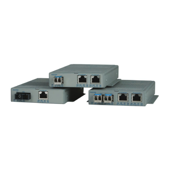
Page 1: User Manual
OmniConverter ™ FPoE/SL User Manual 140 Technology Dr., #500 Irvine, CA 92618 USA Phone: (949) 250-6510; Fax: (949) 250-6514... -
Page 2: Warranty
Powered Device (PD). inadequate use and/or maintenance of the equipment by Buyer, Buyer-supplied The OmniConverter FPoE/SL supports IEEE 802.3af PoE standard and provides up equipment, Buyer-supplied interfacing, unauthorized modifications or tampering to 15.4W of DC power to each PD. - Page 3 SW3, SW4 and SW5 UTP Configuration DIP-Switches UTP Mode of Operation AN/MAN 100/10 FDX/HDX The UTP port is set to auto-negotiation with the following modes advertised: 100FDX, 100HDX, 10FDX, 10HDX The UTP port is set to auto-negotiation with the following modes advertised: 100HDX, 10FDX, 10HDX The UTP port is set to auto-negotiation with the following modes advertised: 10FDX, 10HDX...
- Page 4 SW9, SW10 and SW11 - Power Sourcing Options PoE Option RJ-45 Pinout The UTP ports can be configured to support different powering options. The Alternative A Alternative B powering options include Alternative A (supporting power on pins 1,2 and 3,6), Vport Positive Alternative B (supporting power on pins 4,5 and 7,8) and legacy Power Devices Vport Positive...
- Page 5 2) Apply AC Power SW12 SW13 Function To power the unit using the AC/DC adapter, connect the AC/DC adapter to the DOWN DOWN Link Segment (LS) AC outlet. Route the power cord through the provided strain relief for additional Asymmetrical Link Propagate Port 1 to Port 2 (1+1 - 2 Port models), Port 1 to Port 2 and Port 3 (1+2 - 3 Port models), support.
- Page 6 3) Apply DC Power of power. Power source should be available within 5 ft. of the chassis. The over current Installation of the equipment should be such that the air flow in the front, back, protection for connection with centralized DC shall be provided in the building side and top vents of the chassis are not compromised or restricted.
-
Page 7: Connect Cables
4) Connect Cables 5) Verify Operation Verify the OmniConverter is operational by viewing the LED indicators. a. When using the SFP model, insert the SFP Fiber transceiver into the SFP receptacle on the front of the module (see the SFP Data Sheet 091-17000-001 Power LED Indicators for supported Fast Ethernet transceivers). -
Page 8: Specifications
Specifications UTP Port Indicators Legend Indicator Description Model Type OmniConverter FPoE/SL No link Standard (PoE) IEEE 802.3af Green - ON Port linked at 10Mbps Max PoE Power 15.4W Green - Blinking at 10Hz Port data activity at 10Mbps (per UTP port) Amber - Blinking at 1Hz Port linked at 10Mbps and receiving AN Remote Fault Fiber:... -
Page 9: Appendix A: Link Modes
Appendix A: Link Modes Page 16 Page 17... -
Page 10: Customer Support Information
Customer Support Information If you encounter problems while installing this product, contact Omnitron Technical Support: Phone: (949) 250-6510 Fax: (949) 250-6514 Address: Omnitron Systems Technology, Inc. 140 Technology Dr., #500 Irvine, CA 92618, USA Email: support@omnitron-systems.com URL: www.omnitron-systems.com 040-09340-001A 12/10...
Need help?
Do you have a question about the OmniConverter FPoE/SL and is the answer not in the manual?
Questions and answers