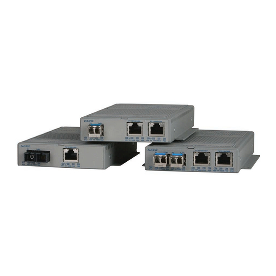
Summary of Contents for Omnitron Systems Technology OmniConverter GPoE+/S
-
Page 1: User Manual
OmniConverter ™ GPoE/S and GPoE+/S User Manual 140 Technology Dr., #500 Irvine, CA 92618 USA Phone: (949) 250-6510; Fax: (949) 250-6514... -
Page 2: Warranty
15.4W of DC power to each PD. with equipment (including removal of equipment cover by personnel not specifically The OmniConverter GPoE+/S supports IEEE 802.3at PoE+ standard providing up authorized and certified by Omnitron), or misuse, or operating outside the to 25.5W of DC power to each PD. - Page 3 accept 1000BASE-X SFPs. Setting these DIP-switches to the Up “100” position enables the fiber port to accept 100BASE-FX SFPs. When an RJ-45 transceiver is installed in a SFP receptacle or for fixed fiber models, setting this DIP-switch to Up “100” position enables the port to operate at 100Mbps*.
- Page 4 Select the appropriate powering source option based on the PD type. Use the SW8 - Power Sourcing Function, UTP Port following table to determine the compatibility of the PD. This DIP-switch controls the power sourcing function for the 2nd UTP port on the 2 UTP port models (see DIP-switch Definition table on page 4).
- Page 5 UTP Port 2 does not cause the loss of link to propagate. The loss only propagates Switch 15 Switch 16 Function in the Port 1 to Port 2 direction. See Port Configurations on Page 3. P1+P2 Redun Rtn P1 DOWN (Off) DOWN (Off) Non-redundant mode - normal mode Note: A loss of link or loss of signal is when the optical receiver on the media converter...
- Page 6 3) Apply DC Power Connect the power wires to the circuit breaker and switch the circuit breaker ON. If any modules are installed, their Power LED should indicate the presence Power source should be available within 5 ft. of the chassis. The over current of power.
-
Page 7: Connect Cables
4) Connect Cables 5) Verify Operation Verify the OmniConverter is operational by viewing the LED indicators. a. When using the SFP model, insert the SFP Fiber transceiver into the SFP receptacle on the front of the module (see the SFP Data Sheet 091-17000-001 Power LED Indicators for supported Gigabit and Fast Ethernet transceivers). -
Page 8: Specifications
Specifications UTP Port Indicators Legend Indicator Description Model Type OmniConverter GPoE/S No link Standard (PoE) IEEE 802.3af Green - ON Port linked at 100Mbps Max PoE Power 15.4W Green - Blinking at 10Hz Port data activity at 100Mbps (per UTP port) No link Protocols (Ethernet) Fiber:... -
Page 9: Appendix A: Link Modes
Appendix A: Link Modes OmniConverter Model Type GPoE+/S Standard (PoE) IEEE 802.3at Max PoE Power 25.5W (per UTP port) Protocols (Ethernet) Fiber: 100BASE-FX, 1000BASE-X UTP Copper: 10/100/1000BASE-T Copper Connectors RJ-45 Fiber Connectors SFP: Dual Fiber: SC, ST Single-Fiber: AC Power requirements 100 to 240VAC / 50 to 60HZ (typical) 460mA@120VAC... -
Page 10: Customer Support Information
Customer Support Information If you encounter problems while installing this product, contact Omnitron Technical Support: Phone: (949) 250-6510 Fax: (949) 250-6514 Address: Omnitron Systems Technology, Inc. 140 Technology Dr., #500 Irvine, CA 92618, USA Email: support@omnitron-systems.com URL: www.omnitron-systems.com 040-09400-001D 12/10...


Need help?
Do you have a question about the OmniConverter GPoE+/S and is the answer not in the manual?
Questions and answers