Advertisement
406-S
ENROULEUR DE FOC - NOTICE D'UTILISATION
ROLLREFFANLAGE - AUFBLASBARE RETTUNGSWESTEN
ROLREEFSYSTEEM - GEBRUIKERSHANDLEIDING
RULLFOCKSYSTEM - INSTRUKTIONER OCH HANDHAVANDE
Plastimo - 15, rue Ingénieur Verrière - 56100 Lorient - FRANCE
609-S
JIB REEFING - OWNER'S MANUAL
ENROLLADOR - GUIA DE UTILIZACION
AVVOLGITORE - MANUALE D'USO
811-S
GB
F
D
NL
E
S
I
Advertisement

Subscribe to Our Youtube Channel
Related Manuals for Plastimo 406-S


Summary of Contents for Plastimo 406-S
- Page 1 JIB REEFING - OWNER'S MANUAL ENROULEUR DE FOC - NOTICE D'UTILISATION ROLLREFFANLAGE - AUFBLASBARE RETTUNGSWESTEN ROLREEFSYSTEEM - GEBRUIKERSHANDLEIDING ENROLLADOR - GUIA DE UTILIZACION RULLFOCKSYSTEM - INSTRUKTIONER OCH HANDHAVANDE AVVOLGITORE - MANUALE D'USO Plastimo - 15, rue Ingénieur Verrière - 56100 Lorient - FRANCE...
- Page 3 ØB ØA Ø31 Ø200 Ø190 Ø145 ØH ØH ØH 406-S 609-S 811-S stevenplaa- spanschroe- Terminal- Stagspanner- tensor chainplate turnbuckle latte ridoir placas Landre Arridatoi montage tuitvoering fuitvoering montage 406-S 25722 25723 25722 25723 25722 25723 25722 25723 25722 25723 25723...
- Page 4 406-S 1 Trumma med 1 drum unit 1 ensemble tambour 1 Trommel 1 roltrommel 1 conjunto tambor 1 insieme tamburo revlinematare 1 halyard swivel 1 émerillon 1 Fallwirbel 1 valwartel 1 giratorio 1 Fallsvirvel 1 mulinello 1 boltrope prefeeder 1 guide ralingue 1 Liekeinführung...
- Page 5 609-S 1 Trumma 1 drum unit 1 ensemble tambour 1 Trommel 1 roltrommel 1 conjunto tambor 1 insieme tamburo 1 halyard swivel 1 émerillon 1 Fallwirbel 1 valwartel 1 giratorio 1 Fallsvirvel 1 mulinello 1 boltrope prefeeder 1 guide ralingue 1 Liekeinführung 1 voorlijkinvoer 1 guía relinga...
- Page 6 811-S 1 conjunto tambor 1 insieme tamburo 1 drum unit 1 ensemble tambour 1 Trommel 1 roltrommel 1 Trumma 1 halyard swivel 1 giratorio 1 émerillon 1 Fallwirbel 1 valwartel 1 Fallsvirvel 1 mulinello 1 boltrope prefeeder 1 guide ralingue 1 Liekeinführung 1 voorlijkinvoer 1 guía relinga...
-
Page 7: Table Of Contents
ASSEMBLY INSTRUCTIONS FOR S-SERIES 406-S 609-S 811-S I N D E X 1/ TECHNICAL SPECIFICATIONS 406-S, 609-S, 811-S 2/ DESCRIPTION OF SPECIFIC PARTS FOR EACH MODEL 2.1 - 406-S 2.2 - 609-S 2.3 - 811-S 3/ TOOLS NEEDED 4/ FLAT ASSEMBLY (forestay dismantled)) 4.1 - Dismantling the forestay... - Page 8 4.1 - Dismanting the forestay 4.1.1 - Lower part - Slacken the backstay - Secure the mast forward with 1 or 2 halyards - Tigthen the halyards to relieve the strain on the forestay slackened - Dismantle the lower part of the forestay (this usually consists of removing a removing a backstay forestay rigging screw pin, or a screw and a nut).
- Page 9 - Slide the base spar into the drum unit until the two holes are in line, insert the M5x12 screw (after putting some silicone filler in the hole in order to reduce the stainless steel / aluminium electrolytic couple) and tighten. - Install the boltrope prefeeder;...
- Page 10 4.4 Installing the top end stop - Slot the second bearing into the top end stop - Slide the top end stop over the aluminium spar - Drill a hole (with a Ø4 mm drill). IMPORTANT: refer to diagram for the positioning of the top end stop - Before putting the screw into position, do not forget to slide the halyard swivel into place (ensure that the conical end of the halyard swivel faces downwards) - Put the top end stop back into position...
-
Page 11: Assembling The Top End Stop
5.2 - CUTTING THE LAST SPAR - Stretch out flat the piece of rope used to measure the length of the forestay - Lay the aluminium spars parallel to the piece of rope (take note of base spar, see page 7) - Mark the spar level with the mark on the piece of rope - Cut the spar 3 cm (safety margin) below the mark 5.3 - ASSEMBLING THE TOP END STOP... -
Page 12: Assembling The Base Spar
- Refasten the forestay - Attach a halyard to the halyard swivel in order to support the spars as they are assembled - Insert a coupling sleeve - Put some silicone filler into the holes before tightening the screws (in order to reduce the electrolytic couple between the stainless steel screw and the aluminium) - Insert an M5 x 8 screw - Wipe away any excess silicone with a cloth... -
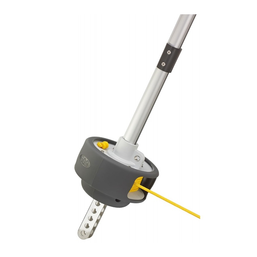
Page 13: Assembling The Drum Unit
5.9 - ADJUSTING THE REEFING LINE FEEDERS 5.9.1 - 406-S model - The reefing line feeder on the 406-S model is assembled either on the right or left hand side of the drum unit, depending on which direction you prefer to reef. -
Page 14: Recommandations
6/ Recommandations Reefing line feeders The angle of all the reefing line feeders may be adjusted. IMPORTANT: they should be positioned in a way that best suits the direction of pull on the line Reefing line The reefing line is wound around the drum. Only use pre-stretched rope in order to eliminate any elasticity Refer to diagram below for the position of the reefing line as it comes out of the drum 90°... -
Page 15: Optional Extras
PROBLEM ENCOUNTERED CAUSES SOLUTIONS Halyard turns with the halyard swivel - Forestay not taut enough - tighten the backstay - Genoa halyard too slack - tauten the genoa halyard - Genoa too short, halyard swivel too low - Use a strop - Genoa halyard too close to the forestay - Fasten a halyard feeder to the mast or a diverter to the forestay...
Need help?
Do you have a question about the 406-S and is the answer not in the manual?
Questions and answers
We have just fitted a Plastimo furler. To my dismay our genoa would not fit as the luff appears to be to thick. Is this a common occurrence? Please advise
Yes, it is common for a Plastimo 406-S furler to have issues if the genoa luffrope is too large. The context mentions "Luffrope too large – Change luffrope" as a solution, indicating that this can cause problems with the furler's operation.
This answer is automatically generated