
Subscribe to Our Youtube Channel
Related Manuals for Gatekeeper Systems 304-SD


Summary of Contents for Gatekeeper Systems 304-SD
- Page 1 Safety, Security, Peace of Mind Gatekeeper Systems 304-SD Solid State System. - 1 - 304-SD Install and User Guide V1.2 DN2715...
-
Page 2: Table Of Contents
CONTENTS TABLE OF FIGURES................................4 LIST OF TABLES ..................................5 INTRODUCTION ..................................6 GLOSSARY....................................6 IMPORTANT SAFEGUARDS AND WARNINGS......................... 7 PACKAGE CHECK LIST................................. 8 DOWNLOAD KITS ................................... 9 ................................. 9 SD D OWNLOAD SD D A ..............................9 OWNLOAD SD D B .............................. - Page 3 ..................................25 VENT ILES ADVANCED CONFIGURATION............................26 SYSTEM ....................................26 DATE TIME ..................................26 REGISTER INFO ................................. 27 FORMAT ....................................28 UPGRADE ................................... 28 USER SECURITY ................................29 CONFIG ....................................29 SYSTEM LOG..................................30 GEO FENCING ..................................30 RECORD ....................................
-
Page 4: Table Of Figures
FIGURE 1: FRONT VIEW ................................................ 10 FIGURE 2: REAR VIEW ................................................11 FIGURE 3: ACCEPTABLE MOUNTING..........................................13 FIGURE 4: 304-SD WIRING, INCLUDING OPTIONAL ACCESSORIES............................... 14 FIGURE 5: POWER CONNECTIONS..........................................14 FIGURE 6: SENSOR CONNECTION EXAMPLE ......................................15 FIGURE 7: SENSOR SETUP ..............................................15 FIGURE 8: INERTIA, G- SENSOR WIRING. -
Page 5: List Of Tables
FIGURE 19: UPGRADE DIALOG WINDOW........................................29 FIGURE 20: CONFIGURATION DEFAULT / IMPORT / EXPORT................................29 FIGURE 21: RECORD OPTIONS ............................................30 FIGURE 22: CAMERA NAME / CHANNEL NUMBER....................................32 FIGURE 23: RECORD SETTINGS ............................................32 FIGURE 24: LOCAL NETWORK SETTINGS........................................35 FIGURE 25: EXAMPLE WI-FI CONFIGURATION. -
Page 6: Introduction
In place of a spinning hard drive the 304-SD records to a removable SD memory card. Utilizing state of the art surface mount components the 304-SD is built to withstand the shock and vibration of vehicle operation. In order to play back the recorded video the 304-SD utilizes custom video viewing software, the “G4 Viewer”, a very easy to use application which allows users to... -
Page 7: Important Safeguards And Warnings
DVR warranty will be void. The 304-SD has an operating temperature range of -40° C to +65° C. It is good practice to ensure that the 304- SD is mounted in an area in which acceptable temperature ranges are experienced. -
Page 8: Package Check List
Package Check List. Ensure all system components are accounted for prior to installation. Contact Gatekeeper Systems, Inc. if any components are missing or if they appear defective. 304-SD Mobile Digital Video Recorder. Power Cable: P/N: CAB000309 Sensor Cable: P/N: CAB000323... -
Page 9: Download Kits
Download Kits Gatekeeper Systems offers additional Download Kits which enhance the usability of the 304SD. These download kits have been designed to assist in the management; configuration and maintenance of the 304SD. SD Download Kit Part Number = G4SDDLK Contains: ... -
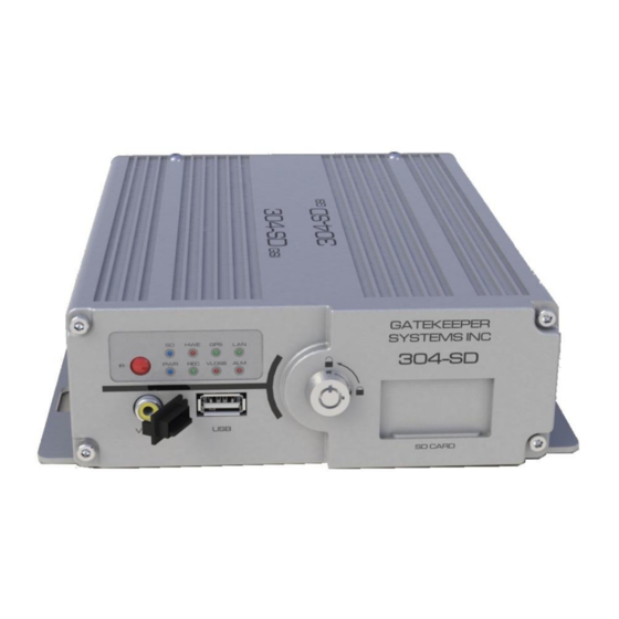
Page 10: System Overview
System Overview. Front View Figure 1: Front View 1. LED Status Indicators. (See Table 1) V OUT. Connects to External Display 3. USB. Used for Saving/Uploading configurations and Lock. Allows access to the SD Card Slot (5) and can updating the system firmware. start &... -
Page 11: Rear View
Rear View 1. Camera Inputs. The 304SD accommodates up to four video channels. Use CAB GSWHC2N-XX (Where XX = Length in Feet, e.g. GSWHC2N-15 for a 15 foot cable. 2. Sensor Connector. CAB000323, Connects to Stop Arm; Warning Lights, etc. 3. -
Page 12: Mounting The System
Mounting the System. Installation / Environmental Requirements. The 304-SD has an operating temperature range of -40° C to +65° C. It is good practice to ensure that the 304-SD is mounted in an area in which acceptable temperature ranges are experienced. -
Page 13: Mount In Bulkhead
As the bulkhead area is not heated or cooled it is subject to temperature extremes. In order to implement best practices Gatekeeper Systems recommends that the 304-SD mounted in the passenger compartment that is heated and cooled. By avoiding temperature extremes (hot and cold) the components in the 304-SD DVR will be subject to less temperature stress. -
Page 14: Power Connector (Cab000309)
Figure 4: 304-SD Wiring, Including Optional Accessories. Connection Bundles. Cable Length (Nominal) SENSORS IN : 1- 6 (see for configuration) 16 ½ Feet SENSORS IN : 7 – 8 (Currently not used) 8 Inches SENSORS OUT : 1- 2 8 Inches SPEED + / - (not supported) 7.8 Inches... -
Page 15: Sensors
Sensors The 304-SD allows for up to six sensor inputs, all of which are user configurable, with Sensor 1, 2 and 3 being pre-configured in the DVR, see table below. The wire from these Six sensor connections are approximately Five meters long. -
Page 16: Gps
The 304-SD can be outfitted with an optional GPS module. For optimum results it is recommended that the GPS module be exterior mounted utilizing the magnetic base with the cable protected by a suitable grommet. If it is not possible/practical to have the GPS module exterior mounted, the GPS module must be mounted internally with a direct line of sight vertically skyward. -
Page 17: Driver Alert Button
Driver Alert Button. A Driver Alert Panel is available as an optional accessory for the 304-SD. The Driver Alert Panel must be installed using the provide Tek screws. The Driver Alert allows for the driver of the vehicle to press the button and mark the recorded video with an Alert. -
Page 18: Sd Card - Overview
SD Card – Overview. The 304-SD utilizes a SD (Secure Digital) card for the storage of Video. SD cards are very simple to use, and very reliable. The SD cards supplied by Gatekeeper Systems have been extensively tested and are the only approved SD cards for use in the 304-SD. -
Page 19: Using The Remote Control
Using the Remote Control. Use the ARROW keys to move between selections, input fields and icons. Press ENTER to select. And EXIT to return. Next and previous is also used to increase or decrease volume when at live or search screens. Use the numbers to input Values during system setup, Screen, or switch through the channels in live and playback. -
Page 20: System Configuration
System Configuration The 304-SD utilizes a simple three option menu system. Going from Left to Right the Quick Configuration gives access to the vast majority of required menu options, the basic settings which need to be set for each individual 304-SD for effective operation. -
Page 21: Camera Name
ON or OFF, except for position which has a TOP or BOTTOM option. LIVEVIEW controls what will be visible when the output of the 304-SD is viewed either via the ICD accessory, or, the RCA output connection on the front of the Digital Video Recorder. -
Page 22: Date/Time
There are 8 options available for setting within the Speed option. Some of these options are only available after other selections have been made. Please Note: An approved GPS antenna should be connected to the 304-SD to receive satellite signals for speed. 22 -... -
Page 23: Format Card
304SD. A confirmation window will appear stating that the 304-SD is restarting. NOTE: If a SD card has been formatted in a PC or another device, it MUST be formatted in the 304-SD. In order to increase reliability as a custom file system is utilized by the 304-SD. The SD card must be formatted on the 304-SD or no video will be recorded. -
Page 24: Recorded Video
Unlocks Event files allowing them to be overwritten EXPORT Exports the selected files to an external USB device connected to the front of the 304-SD EXIT Exits the File List page and returns the user to the File Search page. -
Page 25: Event Files
In the example on the right, Channels 1 and 2 of the file timed at 09:08:24 have been selected for Exporting to an external USB drive. Use the remote control to Arrow over to the SEL area of the required file and press Enter. -
Page 26: Advanced Configuration
Select ALL files for Exporting and an X will display under the SEL column for all files. EXPORT Export the selected Files to external USB drive connected to the front of the 304-SD. Advanced Configuration. There are six menu options listed under Advanced Configuration. -
Page 27: Register Info
Event Files can be automatically download if this menu option is set to ON. Please Note: Only Event Files for the current day will be downloaded to the USB drive via the 304-SD’s front connection; e.g. if Todays date is 01/02/2013 then ONLY event files dated 01/02/2013 will be automatically downloaded to the external USB drive. -
Page 28: Format
FORMAT Use this feature to format devices ready for use with the 304-SD. Use the remote control to highlight the required option and then press Enter to open the Options drop down window. Please note that Format will erase all data from the device being formatted. This erased data cannot be retrieved. -
Page 29: User Security
Exports the current configuration. Use a USB drive connected to the front of the 304-SD to download Export the configuration too. The configuration file name will be saved as MDVRCFG.CFG This file name MUST not be changed or any 304-SD which you attempt to Import this configuration too will not see the file. -
Page 30: System Log
The 304-SD will begin recording at the time specified in the Timer Record menu based on the schedule Event: When an Event has been triggered the 304-SD will record. To set an Event to record go to Advanced Configuration System Event to set triggers. Default: General Normal Rec Rate Options: Normal or I Frame. -
Page 31: Osd Overlay
ON or OFF, except for position which has a TOP or BOTTOM option. LIVEVIEW controls what will be visible when the output of the 304-SD is viewed either via the ICD accessory, or, the RCA output connection on the front of the Digital Video Recorder. -
Page 32: Camera Setting
CAMERA SETTING. Camera Setting options controls what will be displayed on the On Screen Display and/or what will be recorded. The Enable value can either be ON or OFF. If the CH1, 2, 3 or 4 value is set to ON the text entered into the NAME field will display on the OSD. -
Page 33: Other Setting
Reserved for future development. The 304-SD will record as normal. NORMAL: The 304-SD will record Events ONLY during the time specified in the schedule. ALARM: SCHEDULE 2 00:00-00:00 This defines the schedule for a second cycle on the same day if required. -
Page 34: Network
PC/Server to the 304-SD, or, when using an external Wi-Fi radio. Mobile Net Allows connection to the 304-SD via 2G/3G cellular networks. Wi-Fi Net Select this value when the 304-SD is going to use the internal Wi- Fi module for communications. MESSAGE SERVER OPTIONS Domain Name If a fully qualified domain name is available, this option can be utilized. -
Page 35: Local
LOCAL Local settings are used to allow the 304-SD to have network connectivity either through an external wi-fi module, or, direct connection to a network switch/hub. The IP Information listed is a default setting for use with an approved Gatekeeper Systems Inc. -
Page 36: Wi-Fi
Please note: This function is currently reserved for future development. If a mobile network is to be configured, the 304-SD will require the installation of a SIM card. The installation of the SIM card must be done at time of system build at the Gatekeeper Systems Facility. -
Page 37: Ftp Settings
There are 8 options available for setting within the Speed option. Some of these options are only available after other selections have been made. Please Note: An approved GPS antenna is required for the 304-SD to receive satellite signals for speed. -
Page 38: Acceleration
ACCELERATION If the 304-SD has been fitted with an Inertia, G, Sensor this can be setup with independent values for X, Y and Z axis, these can be set to the requirements of the individual customer. The Inertia sensor can be tested by accessing the Check Button, System ... -
Page 39: Voltage
Voltage Low Voltage Protection is OFF by default. If Enabled Highs; Lows and Measurements in-between will be displayed as part of the Device Status within G4 viewer. Emerg. Alarm Determines if the Driver Alert Button will activate an alarm when pressed by the driver of the vehicle. If Alarm is set to ON a marker will appear as part of the OSD and video playback file. -
Page 40: Info
Info Version Displays the current version of Firmware installed on the 304-SD. The SD Total Capacity; Amount of Available free space and total recording time, in hours, still available. History Info. History Info display information for the following four items, all of which can be reset to zero by highlighting the CLEAR button and then pressing the ENTER button on the remote control. -
Page 41: Overview
Administrator rights. For more information on this, please speak with your School District’s Information Technology contact. This section will describe how to install Gatekeeper Systems Inc. G4 Incident Management Software. Please read before beginning the install. G4 Incident Management Software can be installed from the G4 CD (available as part of G4HDDLK), or, as a free download from The Gate area of www.gatekeeper-systems.com... - Page 42 In the window which appears next make sure that “Don’t create a Start Menu Folder” is not checked. Click Next. Select “Create a Desktop Icon” and click Next. A window stating Ready To Install will appear, click on Install. An Install Progress window will appear. Once Setup has completed the Completing The G4 Viewer Setup Wizard will appear.
-
Page 43: G4 Playback Interface
G4 Playback Interface. Do not format the SD card using Microsoft Windows. Figure 29: G4 Incident Management Software Interface 1. Displays the installed version of G4; Current System 2. GSI Logo. When Clicked opens www.gatekeeper- Date/Time. systems.com 3. Video Playback Window, HDD. -
Page 44: Hdd
When viewing recorded video from a 304-SD using the SD card, HDD will display the vehicle name. Double click on the listed vehicle and all available video on the SD card will be displayed in the Calendar. Double click on one of the highlighted days and the Playback Setup dialog window will appear. -
Page 45: Device
Device. Device lists all the 304-SD’s which have been configured to utilize Gatekeeper Systems Inc. MeteorMax Wireless System. This setup and configuration is covered in more depth in a separate document. Opening Screen. When G4 Viewer is first launched, the opening screen will display these four initial icons. -
Page 46: Time Bar
In the example on the right, there are only two video files for the vehicle’s morning run, these are shown as GREEN in the Time Bar. If the 304-SD has been set up for recording Alarms, the video files available will be displayed as RED. -
Page 47: Snapshot / Clip / Open File / Layout Controls
Snapshot / Clip / Open File / Layout Controls. With the video paused at a specific image, if the Snapshot (Camera) Icon is clicked a snapshot will be sent to the folder previously setup in System Setting (Item 17 in Figure 29). To the right is a pop up menu with an option to Open Folder, this will open the folder to which the snapshot has been saved. -
Page 48: Event Playback
If an individual Event is selected (2) the playback video will jump to that position and the Event list window will highlight the current Event selection. The Event number, as set up in the 304-SD configuration, will also be displayed, (3). -
Page 49: Sensor / Alarm Playback 2
Sensor / Alarm Playback 2. In playback Mode it is also possible to have the Time Bar just display Sensor markers rather than All Channels. If Sensor is selected the Time Bar will display Markers when a Sensor was activated. Use the Zoom in tool to expand the Time Bar making it easier to select an individual Sensor Marker. - Page 50 2. Click on the Zoom in Time Bar icon until a suitable time frame appears. 3. Select the Start Point and Click and Drag it to the required Start point before the required clip. Next select the End Point and Click and Drag this to the end of the required clip.
-
Page 51: Exporting A Clip
7. If you navigate to the folder setup in G4 System Settings, you will see a folder with the date of the clip as its title, in this example 2014-01-28: January 28 2014. Exporting a Clip. When a clip is exported a standalone .exe file is created. This allows the clip to be distributed without the need to install G4 Incident Management Software. -
Page 52: Blurring An Image
Blurring an Image. G4 Incident Management Software has a Blur feature allowing individual elements in a video file to be effectively “screened-out” of the playback. To Blur an area of the playback video first pause the video playback and then give a single camera the focus in the playback window. -
Page 53: Appendix
The audio hole on the front of the camera can be used as an aiming guide for the direction the camera needs to be facing. All camera harnesses must be carefully routed to the 304-SD unit to avoid pinching or piercing the shielded camera cable. ... -
Page 54: Suggested Camera Locations
7. To aim the Camera Ball (C), video from the camera can be viewed by connecting a portable LCD/Monitor with an RCA connection to the front of the 304-SD, or, by use of the ICD accessory available from Gatekeeper Systems. - Page 55 Wire Routing: Camera harness to be connected through opening in base. Use existing wire paths wherever possible, radio, speakers, etc. Avoid excessively tight bends especially around metal surfaces. Always use grommets when routing through sheet metal holes. ...
-
Page 56: Video Alignment Cable: Cab000157
I: Red RCA Audio Output to Audio Input on Portable LCD or DVD Player. An installed, fully functional, powered up 304-SD is required when using CAB000157 Video Alignment Cable. If you look at the Video Alignment Cable you will see that there are three cables coming from one end of the Video Alignment Cable and a single cable coming from the other end. -
Page 57: 304-Sd Quick Install Guide
Quick Configuration Guide. The 304-SD firmware must be configured before using the DVR. Connect a monitor to the RCA Video Out port on the front of the 304-SD. Press the Setup key on the IR Remote Control. Enter the following login information when prompted:... -
Page 58: Table 8: Led Status (Record Mode)
DVR prior to use. Start the vehicle and wait for the 304-SD to boot up, approximately one minute. Confirm live camera video is visible on small monitor (small Red R in each camera image – indicates the DVR is recording). Confirm DVR is recording by observing the LED’s as per the following table:... -
Page 59: Warranty
Gatekeeper Systems’ is not responsible for lost or missing video. or supplied by Gatekeeper Systems and found in the reasonable judgment of Gatekeeper Systems to be defective in material or workmanship will be repaired or The warranty does not extend to repairs made necessary by normal wear or replaced by Gatekeeper Systems without charge for parts and labor. -
Page 60: Contact Information
Contact Information. GSI – Canada 301-31127 Wheel Avenue Abbotsford, BC V2T 6H1 Canada GSI – USA 446 Harrison Street Sumas, WA 98295 Sales & Technical Support North America: Tel: 1.604.864.6187 Fax: 1.604.864.8472 Toll Free: 1.888.666.4833 60 -...
Need help?
Do you have a question about the 304-SD and is the answer not in the manual?
Questions and answers