
Subscribe to Our Youtube Channel
Related Manuals for Gatekeeper Systems 816-HD


Summary of Contents for Gatekeeper Systems 816-HD
- Page 1 Safety, Security, Peace of Mind 816-HD USER GUIDE AND MANUAL DN2778_816HD_UserGuideManual 2014-02-25...
-
Page 2: Table Of Contents
Table of Contents. TABLE OF FIGURES..............................................5 Introduction ................................................. 6 Glossary ..................................................6 Important Safeguards and Warnings......................................7 Package Checklist..............................................8 Download Kits ................................................9 HD Download Kit..............................................9 HD Download Kit Plus A ........................................... 9 HD Download Kit Plus B ........................................... 9 System Overview.............................................. - Page 3 OPTIONS 2................................................24 OSD OVERLAY ..............................................24 CAMERA SETTINGS............................................25 RECORD SETTING............................................25 MIRROR RECORD SETTINGS........................................26 SUB STREAM ..............................................26 SCHEDULE ................................................26 OTHER SETTING ..............................................27 NETWORK ................................................28 LOCAL ..................................................28 SERVER ................................................. 28 WIFI ..................................................
- Page 4 Time Bar................................................41 Calendar or Playback Interface........................................41 Playback Details..............................................41 Playback Controls............................................. 41 Snapshot / Clip / Open File / Layout Controls.................................. 42 System Settings..............................................42 Playing Back a Video File............................................ 43 Event Playback................................................ 43 Sensor / Alarm Playback 1.
-
Page 5: Table Of Figures
TABLE OF FIGURES. FIGURE 1: 816-HD FRONT VIEW..........................10 FIGURE 2: 816-HD REAR VIEW..........................11 FIGURE 3: SENSOR CONNECTION EXAMPLE ....................... 12 FIGURE 4: SENSOR SETUP............................13 FIGURE 5: REMOTE CONTROL........................... 16 FIGURE 6: REC SEARCH............................17 FIGURE 7: EVENT SEARCH. -
Page 6: Introduction
Utilizing state of the art surface mount components the 816-HD is built to withstand the shock and vibration of vehicle operation. In order to play back the recorded video the 816-HD utilizes custom video viewing software, “G4 Viewer”, which is a very easy to use application which allows users to quickly find the video of interest and save a clip. -
Page 7: Important Safeguards And Warnings
816-HD system. If this firmware is applied to any other Gatekeeper Systems DVR warranty will be void. The 816-HD has an operating temperature range of -40° C to +65° C. It is good practice to ensure that the 816-HD is mounted in an area in which acceptable temperature ranges are experienced. -
Page 8: Package Checklist
Package Checklist. 816-HD Digital Video Recorder. Power Cable: P/N: CAB000333 Sensor Cable: P/N: CAB000323 Ignition Line Fuse Power Line Fuse CABLE GUARD Fastening Screws 2 PER UNIT CAB000310 Camera Adapter Cable. 816-HD Mounting Plates (X2) -
Page 9: Download Kits
Download Kits Gatekeeper Systems offers additional Download Kits which enhance the usability of the . These download kits 816-HD have been designed to assist in the management; configuration and maintenance of the 816-HD HD Download Kit Part Number = G4-8XXHDDLK Contains: ... -
Page 10: System Overview
Illuminated when GPS signal is present Displays Network activity When illuminated HDD Heater is active. Illuminated when power present Illuminated when recording. VLOSS Flashes if Video Loss has occurred. Signifies the 816-HD has received an Alarm input. A Physical Hardware error. -
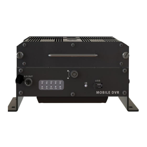
Page 11: Rear View
Installation / Environmental Requirements. The 816-HD has an operating temperature range of -40° C to +65° C. It is good practice to ensure that the 816-HD is mounted in an area in which acceptable temperature ranges are experienced. Please fully read and understand the following conditions to ensure the Warranty will not be voided. -
Page 12: Power Connector (Cab0000333)
Sensors The 816-HD allows for up to six sensor inputs, all of which are user configurable, with Sensor 1, 2 and 3 being pre-configured in the DVR, see table below. The individual wires from these Six sensor connections are approximately Five meters long. -
Page 13: Gps
Driver Alert Button. A Driver Alert Panel is available as an optional accessory for the 816-HD. The Driver Alert Panel must be installed using the provide Tek screws. The Driver Alert allows for the driver of the vehicle to press the button and mark the recorded video with an Alert. -
Page 14: Using The Comrad™ Docking Station
Using the COMRAD™ Docking Station. The 816-HD utilizes a COMRAD™ drive system which can contain up to Two hard disk drives (max 2TB total Capacity) making it extremely portable and thereby easy to download; view and share video files. NOTE: It is essential that the COMRAD™ Docking Station be physically connected to the COMRAD™ and also connected to a PC by using either the supplied USB or ESATA cable prior to the ac power adapter cable being applied. - Page 15 Once the COMRAD™/ COMRAD™ Docking Station/Computer connection has been made, when G4 Incident Management Software is launched underneath the HDD heading the connected COMRAD™/ COMRAD™ Docking Station will appear. Please note that even if the COMRAD™ has two internal Hard Disk Drives only One HDD will appear when the COMRAD™/ COMRAD™...
-
Page 16: Using The Remote Control
Using the Remote Control. Use the ARROW keys to move between selections, input fields and icons. Press ENTER to select. And EXIT to return. Next and previous is also used to increase or decrease volume when at live or search screens. Use the numbers to input Values during system setup, Screen, or switch through the channels in live and playback. -
Page 17: System Configuration
System Configuration The 816-HD utilizes a simple three option menu system. Recorded Video menu option allows for the local playback of previously recorded video files, either by Recorded Search, or, Event Files. The Second menu, System Settings , involves configuration of Networks/Wireless/Cellular, as well as advanced settings for Events/Alarms, etc. -
Page 18: Event Files
VL (Video Loss) and Over Speed. Both of these events have been selected in this screen as can be seen by the X listed under the SEL column. With a USB drive connected to the front of the 816-HD Export can now be selected using the remote control. -
Page 19: System
System. Under System Settings there are Five sub menu’s; System; Record; Network; Event and Peripheral, each with their own sub-menu system. DATE TIME. There are multiple options which the user can select within Date/Time. DATE FORMAT. Once highlighted press the ENTER key on the remote control. Date Format has to be manually entered. Once highlighted, press the ENTER key on the remote control and enter the date in the expected format. -
Page 20: General
01/02/2014 will be automatically downloaded to the external USB drive. Once a USB drive has been connected to the front of the 816-HD press the F1 button on the remote control to initiate auto-download. The USB device must be formatted in the 816- HD prior to exporting of files. -
Page 21: Format
4. Go to the recorder on the vehicle. Connect a portable monitor (or ICD Assembly) to the GSI 816-HD system. Turn the bus ignition on. This should power the unit on automatically. -
Page 22: User Security
EXPORT: Exports the current configuration. Use a USB drive connected to the front of the 816-HD to download Export the configuration to. The configuration file name will be saved as MDVRCFG.CFG This file name MUST not be changed or any 816-HD which you attempt to Import this configuration to will not see the file. -
Page 23: System Log
The 816-HD will begin recording at the time specified in the Timer Record menu based on the schedule Event: When an Event has been triggered the 816-HD will record. To set an Event to record go to System Settings Event to set triggers. Default: General Normal Rec Rate Options: Normal or I Frame. -
Page 24: Options 2
ON or OFF, except for position which has a TOP or BOTTOM option. LIVEVIEW controls what will be visible when the output of the 816-HD is viewed either via the ICD accessory, or, the RCA output connection on the front of the Digital Video Recorder. -
Page 25: Camera Settings
CAMERA SETTINGS Camera Setting options controls what will be displayed on the On Screen Display and/or what will be recorded. The Enable value can either be ON or OFF. If the CAMERA value is set to ON the text entered into the NAME field will display on the OSD. -
Page 26: Mirror Record Settings
OPTIONS: Reserved for future development. Reserved for future development. NORMAL: The 816-HD will record as normal. The 816-HD will record Events ONLY during the time specified in ALARM: the schedule. SCHEDULE 2 00:00-00:00 This defines the schedule for a second cycle on the same day if required. -
Page 27: Other Setting
Liveview is utilized when a portable device such as a DVD player is connected to either of the AV Out connectors; (1) Front of the 816-HD and (2) as part of the DB44 cable (camera fly lead) for initial setup and configuration. -
Page 28: Network
LOCAL Local settings are used to allow the 816-HD to have network connectivity either through an external wi-fi module, or, direct connection to a network switch/hub. Please consult with your I.T. department for all required information relating to IP; DNS Server, etc. if connecting the 816-HD directly to a network 1. - Page 29 PC/Server to the 816-HD, or, when using an external Wi-Fi radio. Mobile Net Allows connection to the 816-HD via 2G/3G cellular networks. Wi-Fi Net Select this value when the 816-HD is going to use the internal Wi-Fi module for communications. MESSAGE SERVER OPTIONS Domain Name If a fully qualified domain name is available, this option can be utilized.
-
Page 30: Wifi
Please note: This function is currently reserved for future development. If a mobile network is to be configured, the 816-HD will require the installation of a SIM card, this must be done at time of purchase of the 816-HD from Gatekeeper Systems as disassembly of the 816-HD in the field will void the warranty. -
Page 31: Event
EVENT SENSOR Sensor setup consists of two pages of options which are user definable. S1; S2 and S3 are pre-defined and factory defaults are set for BRK (Brakes); WRN (Warning Lights) and STPARM (Stop Arm). S7 and S8 are currently unassigned and reserved for future development. The OSD setting is limited to two characters. -
Page 32: Speed
There are numerous options available for setting within the Speed option. Some of these options are only available after other selections have been made. Please Note: An approved GPS antenna is required for the 816-HD to receive satellite signals for speed. -
Page 33: Temperature
ON when there is Video Loss detected the OSD will display an Alarm warning. The VLOSS led on the front of the 816-HD will also be illuminated if video loss occurs. Please note that if no cameras are physically connected to the 816-HD but the corresponding channels have been Enabled, VLOSS will display on the OSD;... -
Page 34: Fatigue Driving
FATIGUE DRIVING. THIS FEATURE IS CURRENTLY NOT SUPPORTED. PERIPHERAL Reserved for future development. EXT. COM COM1 and COM2 are reserved for RS232 connections and are currently not supported. If a Driver Alert Button is to be utilized, COM3 should be set to CONTROL PANEL and MODE set to BUS MODE. -
Page 35: History
HISTORY The History informational page is divided into Three separate dialog windows. History dialog box Page One display’s the Highest Speed recorded by the vehicle and also the Total Mileage since the last time this value was cleared. To Clear a value use the remote control to highlight the word Clear to the Right of the relevant section and then press Enter on the remote control. -
Page 36: G4 Incident Management Software Overview
School District’s Information Technology contact. This section will describe how to install Gatekeeper Systems Inc. G4 Incident Management Software. Please read before beginning the install. G4 Incident Management Software can be installed from the G4 CD (available as part of G4-8XXHDDLK), or, as a free download from The Gate area of www.gatekeeper-systems.com... - Page 37 In the window which appears next make sure that “Don’t create a Start Menu Folder” is not checked. Click Next. Select “Create a Desktop Icon” and click Next. A window stating Ready To Install will appear, click on Install. An Install Progress window will appear. Once Setup has completed the Completing The G4 Viewer Setup Wizard will appear.
-
Page 38: G4 Incident Management Software Interface
HDD. Becomes active when a COMRAD™ is detected on the system. Please Note: When using a COMRAD™ HDD from a 816-HD in a Microsoft Windows based system, you will be prompted to format the COMRAD™, Click CANCEL. If you choose to format the COMRAD™ ALL VIDEO will be deleted from the COMRAD™. -
Page 39: Using G4 Incident Management Software
Using G4 Incident Management Software. When viewing recorded video from a 816-HD using the COMRAD™, Hard Disk will display a single item listed below HDD1, this is also true if the COMRAD™ has Two hard drives fitted internally. Double click on the highlighted COMRAD™ and all available video on the COMRAD™... -
Page 40: Device
Device. Device lists all the 816-HD’s which have been configured to utilize Gatekeeper Systems Inc. MeteorMax Wireless System. This setup and configuration is covered in more depth in a separate document. Opening Screen. When G4 Viewer is first launched and a video clip has been selected, the opening screen will display these four initial icons. -
Page 41: Time Bar
In the example on the right, there are only two video files for the vehicle’s morning run, these are shown as GREEN in the Time Bar. If the 816-HD has been set up for recording Alarms, the video files available will be displayed as RED. -
Page 42: Snapshot / Clip / Open File / Layout Controls
The Zoom-Out icon is the reverse of Zoom-In. Open File. This allows navigation to a known folder containing 816-HD H.264 video files and selecting them for playback. Note only one of the files in the folder in question needs to be highlighted and selected for all of the files in that folder to be played back, Layout. -
Page 43: Playing Back A Video File
If an individual Event is selected (2) the playback video will jump to that position and the Event list window will highlight the current Event selection. The Event number, as set up in the 816-HD configuration, will also be displayed, (3). Sensor / Alarm Playback 1. -
Page 44: Sensor / Alarm Playback 2
Sensor / Alarm Playback 2. In playback Mode it is also possible to have the Time Bar just display Sensor markers rather than All Channels. If Sensor (Item 14 in Figure 20) is selected the Time Bar will display Markers for when a Sensor was activated. - Page 45 2. Click on the Zoom in Time Bar icon until a suitable time frame appears. 3. Select the Start Point and Click and Drag it to the required Start point before the required clip. Next select the End Point and Click and Drag this to the end of the required clip.
-
Page 46: Exporting A Clip
7. If you navigate to the folder setup in G4 System Settings, you will see a folder with the date of the clip as its title, in this example 2014-01-28: January 28 2014. Exporting a Clip. When a clip is exported a standalone .exe file is created. This allows the clip to be distributed without the need to install G4 Viewer. To Export a clip follow Steps 1, 2, 3, 4 in “Saving a Clip”. -
Page 47: Blurring An Image
Blurring an Image. G4 Incident Management Software has a Blur feature allowing individual elements in a video file to be effectively “screened- out” of the playback. To Blur an area of the playback video first pause the video playback and then give a single camera the focus in the playback window. -
Page 48: Appendix
All camera harnesses must be carefully routed to the 816-HD unit to avoid pinching or piercing the shielded camera cable. All cables running through holes in sheet metal (ceiling, bulkhead etc.) must be protected with grommets. - Page 49 7. To aim the Camera Ball (C), video from the camera can be viewed by connecting a portable LCD/Monitor with an RCA connection to the front of the 816-HD, or, by use of the ICD accessory available from Gatekeeper Systems.
-
Page 50: Suggested Camera Locations
Suggested Camera Locations. Check For: Ceiling mount recommended. Do not obstruct walkways. Avoid contact with abrasive metal to prevent short circuits. Three Camera Configuration Wire Routing: Camera harness to be connected through opening in base. Use existing wire paths wherever possible, radio, speakers, etc. -
Page 51: Typical System Wiring Setup
Typical System Wiring Setup. -
Page 52: Cab000323 Db26 Sensor Cable Wiring
CAB000323 DB26 Sensor Cable Wiring. -
Page 53: Warranty
Gatekeeper Systems to be defective in material or workmanship will be altered or modified so as to change its intended use. Gatekeeper Systems’ is not repaired or replaced by Gatekeeper Systems without charge for parts and labor. -
Page 54: Contact Information
Contact Information. GSI – Canada 301-31127 Wheel Avenue Abbotsford, BC V2T 6H1 Canada GSI – USA 446 Harrison Street Sumas, WA 98295 Sales & Technical Support North America: Tel: 1.604.864.6187 Fax: 1.604.864.8472 Toll Free: 1.888.666.4833 E&OE...
Need help?
Do you have a question about the 816-HD and is the answer not in the manual?
Questions and answers