Buffalo BS-GS20 Series User Manual

Buffalo BS-GS20 Series User Manual

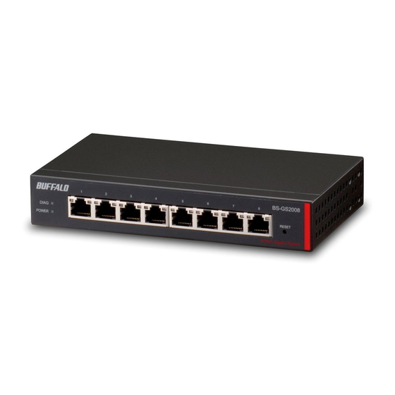
Layer2 gigabit smart switch
Table of Contents

Advertisement

Layer2 Gigabit Smart Switch
BS-GS20 Series
BS-GS20P Series
User Manual
Americas: www.buffaloamericas.com
Europe: www.buffalo-technology.com
35020643-07
2018.10

Advertisement

Table of Contents
loading

Summary of Contents for Buffalo BS-GS20 Series

  • Page 1 Layer2 Gigabit Smart Switch BS-GS20 Series BS-GS20P Series User Manual Americas: www.buffaloamericas.com Europe: www.buffalo-technology.com 35020643-07 2018.10...
  • Page 2: Table Of Contents

    Contents Chapter 1 Initial Settings ..........6 Product Requirements ..............6 Install Business Switch Configuration Tool ........6 Change Switch’s IP Address .............7 Open Settings ...................9 Configure Date and Time .............. 10 Change Username and Password ..........11 MAC Address Learning ..............12 Chapter 2 Settings ............
  • Page 3 LLDP ....................26 LLDP Properties ..................26 LLDP Port ....................27 LLDP-MED Port ..................28 Neighbor Table ..................29 MAC Addresses ................29 Static MAC Filtering .................29 Dynamic MAC Filtering ................30 Convert MAC Address ................31 Static MAC Address ..................31 MAC Address Aging .................31 Port Settings .................. 32 Status ......................32 Speed/Mode Settings ................33 System Security ................
  • Page 4 Port Settings .....................46 IPv4/MAC Priority ..................46 IPv6 Priority ....................47 Status ......................47 Security ..................48 Auto DoS Attack Prevention ..............48 DHCP Snooping ..................49 DHCP Table ....................50 Authentication ................51 Status ......................51 RADIUS ......................52 Port Authentication .................53 Port Trunking ................. 54 Traffic Control ................55 Mirroring ..................
  • Page 5 ACL ....................63 ACL Wizard ....................63 MAC ACL ....................63 IPv4 ACL ....................65 IPv6 ACL ....................66 Ports ......................68 IPv4/MAC Priority ..................68 IPv6 Priority ....................69 Status ......................69 Loop Prevention ................70 DHCP Relay ..................71 Update Firmware ................72 Dual Image ..................72 Back Up and Restore Settings ............
  • Page 6 Chapter 3 Troubleshooting ........80 LED Is Not Lit, Abnormal Lighting or Blinking ......80 Cannot Access Settings ..............80 Forgot the Password ..............80 Appendix A Specifications .......... 81 Product Specifications ..............81 Port Specifications ...................81 Factory Default Settings ............... 82 Restrictions ..................
  • Page 7: Chapter 1 Initial Settings

    Install Business Switch Configuration Tool Install “Business Switch Configuration Tool” before you perform the following procedure. (Compatible with Windows only.) Note: You can download the latest version of Business Switch Configuration Tool from the URLs below: BS-GS2008: http://d.buffalo.jp/BS-GS2008/ BS-GS2008P: http://d.buffalo.jp/BS-GS2008P/ BS-GS2016: http://d.buffalo.jp/BS-GS2016/ BS-GS2016P: http://d.buffalo.jp/BS-GS2016P/...
  • Page 8: Change Switch's Ip Address

    Chapter 1 Initial Settings Change Switch’s IP Address To enter Settings, the switch’s web user interface, the switch’s IP address should belong to the same segment as your PC’s IP address. Connect the switch to your PC and your network with an Ethernet cable (sold separately). Confirm that link/act LED of the connected port is on.
  • Page 9 Chapter 1 Initial Settings Click [Change IP Address]. Configure the switch’s IP address to match the segment of the IP address of your PC and click [Next]. If the password input screen is displayed, enter “password” and click [Next]. Click [Back to Select Switch].
  • Page 10: Open Settings

    Chapter 1 Initial Settings Open Settings Configure the switch’s IP address referring to the “Change Switch’s IP Address” section above. Double-click the “Business Switch Configuration Tool” icon to open Business Switch Configuration Tool. Click [Next] to start searching for the switch. Select the switch and click [Next].
  • Page 11: Configure Date And Time

    Chapter 1 Initial Settings Click [Settings (Web Admin Interface)]. Click OK to launch a web browser and display the login screen. Enter “admin” as the username and “password” as the password, then click [Log In]. Configure Date and Time To configure the date and time, refer to the following procedure. Open Settings.
  • Page 12: Change Username And Password

    Chapter 1 Initial Settings Change Username and Password To change the default username and password from “admin” and “password”, refer to the following procedure. Open Settings. Navigate to [Basic] - [System Security] - [Administration Account]. Enter your new username and password (also fill the “Confirm” field), then click [Apply]. Notes: •...
  • Page 13: Mac Address Learning

    Chapter 1 Initial Settings MAC Address Learning This switch uses SVL (Shared VLAN Learning) to learn MAC addresses. SVL is a method that retains a shared MAC address table for the entire switch. It differs from IVL, which retains a MAC address table for each VLAN. Be sure you understand how SVL works before you create a VLAN with the switch.
  • Page 14: Chapter 2 Settings

    Chapter 2 Settings Chapter 2 Settings Refer to the “Open Settings” section in chapter 1 to access Settings. Menu System Information Displays the switch’s information. Basic System Configure the switch’s name, location, and contact. Confirm VLAN status and create new VLAN. This switch’s IP VLAN Settings address can also be configured on this page.
  • Page 15 Chapter 2 Settings QoS Settings Configure QoS priority. QoS Mapping Configure QoS mapping for each priority. VoIP Auto Priority Configure priority for SIP, H.323, SCCP. DiffServ IPv4/MAC Policy Create DiffServ policies based on IPv4 or MAC addresses. IPv6 Policy Create DiffServ policies based on IPv6 addresses. Port Settings Configure ports to assign each DiffServ policy.
  • Page 16: System Information

    Chapter 2 Settings Dual Image Select a firmware image to be read when booting. Back Up and Restore Settings Save settings to a file or restore settings from a file. Reboot Reboot the switch. Initialize Initialize the switch. Port Order Displays the ARP table ordered by ports.
  • Page 17: System

    Chapter 2 Settings System Configure the switch’s name, location, and contact. Enter the switch’s name. You may enter up to 50 alphanumeric characters, Switch Name hyphens, and underscores. Enter the location of the switch. You may enter up to 50 alphanumeric characters, Location hyphens, underscores, and spaces.
  • Page 18 Chapter 2 Settings Displays current VLAN and PVID (Port VLAN ID) status. Click [Edit] to edit the VLAN VLAN Status selected. Click [Delete] to delete the VLAN selected. VLAN 1 cannot be deleted. VLAN ID Specify VLAN ID from 2-4094. Enter the VLAN name.
  • Page 19 Chapter 2 Settings Method of Acquiring DNS Select a method of obtaining the DNS server’s IP address. Server Address Primary DNS Server Enter the primary DNS server’s IP address. Secondary DNS Server Enter the secondary DNS server’s IP address. IPv6 Check “Enable”...
  • Page 20 Chapter 2 Settings VLAN ID Specify the VLAN ID from 2-4094. Enter the VLAN name. You may enter up to 17 alphanumeric characters, hyphens, VLAN Name and underscores. If an IP address is assigned to the VLAN, that VLAN will become a management Management VLAN VLAN in L3 mode.
  • Page 21: Vlan Ports

    Chapter 2 Settings Enter the default gateway to configure an IPv6 default gateway manually. The Static Default Gateway default gateway prefix should be the same as the static global address. Displays the dynamic global address obtained from DHCPv6 or router advertisement.
  • Page 22: Routing

    Chapter 2 Settings Routing L2/L3 Settings Configure the layer mode of the switch. Specify the layer mode from the following. L3 mode Mode The switch works as a layer 3 switch. L2 mode The switch works as a layer 2 switch. Note: Switching the mode will delete static routing settings and all VLANs except VLAN 1.
  • Page 23: Snmp Settings

    Chapter 2 Settings Add the static routing setting to the table by entering the following items. Up to 32 static routes can be created. Network Static Routing Table Enter the IP address of the network that you need to configure the static routing Setting for.
  • Page 24: Snmp Host Table

    Chapter 2 Settings SNMP Host Table Configure the SNMP host table. Note: To delete the registered host, make “Hostname” and “IP Address” field blank and click [Apply]. Enable/disable SNMP host authentication. Enable SNMP service will be provided from SNMP manager only. Read/write authority Host Authentication depends on the community.
  • Page 25: Snmp Trap

    Chapter 2 Settings SNMP Trap Configure SNMP traps. Note: To use SNMP traps, register the host to the host table on the [Basic] - [SNMP] - [SNMP Host Table] page and enable “trap” for that community. Compatible traps: 0 coldStart 1 warmStart 2 LinkDown (Link Up/Down) 3 LinkUp (Link Up/Down)
  • Page 26: Snmpv3 User

    Chapter 2 Settings SNMPv3 User Configure information of users who are authenticated with SNMPv3. SNMPv3 will authenticate users using username and the authentication can be encrypted. This switch is compatible with the following authentication and encryption method. Authentication method: HMAC-MD5-96/HMAC-SHA-96 Encryption method: CBC-DES/CFB-AES-128 This is the switch’s unique ID to identify SNMP engine.
  • Page 27: Lldp

    Chapter 2 Settings LLDP LLDP Properties Configure LLDP. TLV Advertised Interval Enter the interval of sending LLDP packets. (5-32768 seconds) Enter the amount of time of TTL (Time To Live: the time that LLDP packets Hold Multiplier are held before the packets are discarded) measured in multiples of the TLV advertised interval.
  • Page 28: Lldp Port

    Chapter 2 Settings LLDP Port Configure LLDP for each port. Disable Disable LLDP. Tx Only Enable transmitting LLDP packets only. Status Rx Only Enable receiving LLDP packets only. Tx and Rx Enable transmitting and receiving LLDP packets. If enabled, SNMP traps will be sent to the SNMP server when the neighbor table is updated.
  • Page 29: Lldp-Med Port

    Chapter 2 Settings LLDP-MED Port Configure LLDP-MED for each port. If enabled, LLDP-MED will be transmitted. Status Note: To use this functionality, configure the status to [Tx Only] or [Tx and Rx] on the [LLDP Port] page. If enabled, the SNMP trap will be sent to the SNMP server when the LLDP-MED information in the neighbor table is updated.
  • Page 30: Neighbor Table

    Chapter 2 Settings Neighbor Table Displays the information of the LLDP-compatible devices connected to the switch. MSAP Entry # Displays the entry number of the detected devices. Local Port Displays port number that the detected devices are connected to. Chassis ID Subtype Displays the chassis ID subtype of the detected devices.
  • Page 31: Dynamic Mac Filtering

    Chapter 2 Settings Dynamic MAC Filtering Configure the dynamic MAC filtering that enables you to set the number of MAC address learn limits for each port. Dynamic MAC Filtering Check “Enable” to enable dynamic MAC filtering. Number Enter the number of MAC address learning limits of each port. (1-16384) Notes: •...
  • Page 32: Convert Mac Address

    Chapter 2 Settings Convert MAC Address Add dynamic MAC addresses to static MAC filtering table to filter them in static MAC filtering. Select a port number to display the dynamic MAC addresses that was learned Add to Static MAC Filtering Table from from the port.
  • Page 33: Port Settings

    Chapter 2 Settings Port Settings Status Displays the port status. Name Displays the port name. Admin Displays whether the port is enabled (on) or disabled (off ). Link Status Displays whether the link is up or down. Autonegotiation Displays whether the autonegotiation is enabled (on) or disabled (off ). Speed/Duplex Displays the speed and duplex status.
  • Page 34: Speed/Mode Settings

    Chapter 2 Settings Speed/Mode Settings Configure ports settings such as the transmission rate or flow control. Enter the port name. You may enter up to 15 alphanumeric characters, hyphens, Name underscores, and spaces. Admin Check to enable the port. Mode Select the transmission rate and duplex.
  • Page 35: Access Management

    Chapter 2 Settings Access Management Configure each administration interface. SNMP Enable or disable SNMP administration interface. Enable or disable HTTPS administration interface. HTTPS Note: To use this functionality, upload SSL certificate on the [Basic] - [System Security] - [Certificate] page. Web Session Timeout Enter the timeout period for accessing Settings using HTTP.
  • Page 36: Date & Time

    Chapter 2 Settings Upload HTTPS Certificate Upload HTTPS certificate. to Switch Download HTTPS Download HTTPS certificate. Certificate from Switch Displays the uploaded certificate information. Click [Delete] to delete the uploaded certificate. SSL Certificate Information Note: If the certificate is deleted, a certificate will be automatically created next time the switch reboots.
  • Page 37: Poe

    Chapter 2 Settings This functionality is for PoE-compatible switches only. Status Displays the PoE status. Power Displays the maximum power, power being used, and available power. Displays if PoE is enabled (on) or disabled (off ). Notes: • If you connect a PoE device to the switch while available power (shown to the right of "Available") is 16000 mW (16 W) or lower, the switch will not supply PoE power to the device.
  • Page 38: Poe Profiles

    Chapter 2 Settings PoE Profiles Configure PoE settings for each profile that is used in [Power Profile] page. Profile Name To change the profile name, enter a new profile name and click [Modify]. Enable or disable PoE functionality. Configure the priority of PoE power feeding. When the supplied power exceeds Priority maximum power, the switch will supply power to the ports in the order of priority.
  • Page 39: Power Profile

    Chapter 2 Settings Notes: • Click [Apply] to apply the current settings to all profiles. • To use dynamic power feeding by LLDP, configure the status to [Tx and Rx] on the [Basic] - [LLDP] - [LLDP Port] page. • If the supplied power exceeds the maximum power, the switch will supply power to the port in the order of the port number.
  • Page 40: Qos

    Chapter 2 Settings Select a method of specifying the profile. “Copy profile from a different day” Select Profile cannot be selected when “Day of week and time” is selected as the timetable type. Select a profile name if “Use profile below” is selected as the method of specifying Profile the profile.
  • Page 41: Qos Mapping

    Chapter 2 Settings QoS Mapping Configure port-based priority for DSCP, CoS, and IP precedence. Port Priority Configure the priority of each port. DSCP Mapping Configure the DSCP priority value from 0-63. CoS Mapping Configure the CoS priority value from 0-7. IP Precedence Mapping Configure the IP precedence priority value from 0-7.
  • Page 42: Voip Auto Priority

    Chapter 2 Settings VoIP Auto Priority Configure the priority of SIP, H.323, SCCP. Check to enable VoIP auto priority. Click [Show Detail] to enable or disable this VoIP Auto Priority functionality for each port. Applied to the VoIP packets of SIP, H.323, SCCP only. If QoS is enabled, it is handled in accordance with CoS priority.
  • Page 43 Chapter 2 Settings The following screen appears when [Show Detail] is clicked. Policy Name Displays the selected policy name. Adds the CoS value to the policy condition. Adds the frame’s destination MAC address to the policy condition. For Destination MAC Address instructions on how to enter the address, refer to “About Address and Mask”...
  • Page 44 Chapter 2 Settings Select the action for when the frames satisfy the condition. Permit Permits forwarding the frames and packets. Deny Discards the frames and packets. Egress Queue Changes the processing priority of the frames and packets. Remark CoS Rewrites CoS value of the frames and packets. Remark DSCP Rewrites DSCP value of the frames and packets.
  • Page 45: Ipv6 Policy

    Chapter 2 Settings IPv6 Policy Create DiffServ policies. IPv6 addresses can be specified here. The enabled policies will be applied when the packet or frame enters the switch. Current Number of Displays the number of created policies. Policies Current Number of Active Displays the number of active policies.
  • Page 46 Chapter 2 Settings Select the action for when the frames satisfy the condition. Permit Permits forwarding the frames and packets. Deny Discards the frames and packets. Egress Queue Changes the processing priority of the frames and packets. Remark CoS Rewrites CoS value of the frames and packets. Remark DSCP Rewrites DSCP value of the frames and packets.
  • Page 47: Port Settings

    Chapter 2 Settings Port Settings Configure the ports to apply DiffServ policies. The ports specified by ACL rules cannot be specified. Current Number of Active Displays the number of active IPv4 and MAC address-based policies. Policies Current Number of Active Displays the number of active IPv6 address-based policies.
  • Page 48: Ipv6 Priority

    Chapter 2 Settings IPv6 Priority Configure IPv6 address-based policies priority. Displays the list of IPv6 address-based policies. Policies are listed in order of the IPv6 Policy List priority. Select a policy and enter the policy number that the selected policy moves to Move Policy before (or after).
  • Page 49: Security

    Chapter 2 Settings Security Auto DoS Attack Prevention Configure packets to be dropped. If enabled, the packets whose source IP address and destination IP address are LAND Attack the same will be dropped. If enabled, the packets whose TCP header size is less than 20 bytes will be Minimum TCP Header Size dropped.
  • Page 50: Dhcp Snooping

    Chapter 2 Settings DHCP Snooping Configure DHCP snooping. DHCP snooping is a function to prevent leasing IP addresses when an illegal DHCP server is connected. DHCP Snooping Check to enable DHCP snooping. Add option 82 to the DHCP packets received from DHCP clients. To obtain an IP DHCP Option 82 address from the DHCP server using this functionality, the DHCP server should be compatible with option 82.
  • Page 51: Dhcp Table

    Chapter 2 Settings DHCP Table Displays the DHCP clients that obtained an IPv4 address from the DHCP server via the switch. Up to 256 clients can be listed. Note: DHCP table can be used only when DHCP snooping is enabled. MAC Address Displays the DHCP client’s MAC address.
  • Page 52: Authentication

    Chapter 2 Settings Authentication Status Displays the authentication server and port authentication status. Displays if each server is enabled or disabled, and the server’s IP address and port Primary/Secondary number. Authentication Status Displays the authentication status of each port.
  • Page 53: Radius

    Chapter 2 Settings RADIUS Configure the RADIUS server. Authentication Check to enable authentication server. Authentication Server IP Enter the authentication server’s IP address. Authentication Server Enter the authentication server’s port number. (1-65535) Port Enter the shared secret of the authentication server. You may enter up to 20 Shared Secret alphanumeric characters, hyphens, and underscores.
  • Page 54: Port Authentication

    Chapter 2 Settings Port Authentication Configure authentication settings for each port. Prepare an authentication server (RADIUS server) separately. Authenticate 802.1X based on the port. All devices connected to the port can 802.1X Port communicate after the authentication. Authenticate 802.1X based on the MAC address. Only the authenticated devices 802.1X MAC can communicate.
  • Page 55: Port Trunking

    Chapter 2 Settings The MAC authentication port authenticates using the source MAC address when it receives IP packets. Use the following username and password to authenticate to the RADIUS server. Username: source MAC address Password: source MAC address Example: If the source MAC address of the IP packet is 00:11:22:33:AA:BB, the username and password is the following.
  • Page 56: Traffic Control

    Chapter 2 Settings Notes: • 8 groups can be created in total between LACP and manual creation. Up to 8 port can be set to a group. • The ports in the same trunk group should belong to the same VLAN. •...
  • Page 57: Mirroring

    Chapter 2 Settings Mirroring Configure to monitor the traffic (copy the contents of communication from source to destination). Enable Check to enable mirroring. Source Port Select ports to be monitored. Destination Port Select ports to monitor the traffic. Spanning Tree Protocol STP Settings Configure STP settings.
  • Page 58: Status

    Chapter 2 Settings MSTP Status Displays the MSTI configuration status. Select an MSTI ID and click [Edit] to add or (MSTP only) delete the VLAN ID(s) and change the bridge priority value. Notes: • To use spanning tree, all devices in the segment must be compatible with spanning tree. •...
  • Page 59: Ports

    Chapter 2 Settings Root Bridge Priority Select a root bridge priority of this switch. (STP/RSTP only) Root MAC Address Displays the root bridge’s MAC address. (MSTP only) CIST Root Bridge Priority Displays the CIST root bridge’s bridge priority. (MSTP only) CIST Root MAC Address Displays the CIST root bridge’s MAC address.
  • Page 60: Igmp

    Chapter 2 Settings If enabled, the port will be in forwarding status immediately. It is recommended to enable fastlink to the port a PC is connected to. Disable it if the switch using Fastlink STP is connected to the port. Note: Fastlink is disabled when the port trunking is configured.
  • Page 61: Igmp Querier

    Chapter 2 Settings IGMP Querier If IGMP querier is enabled, IGMP snooping can be enabled even if no multicast router is connected. IGMP Querier Check to enable IGMP querier. IGMP queries will be forwarded from each VLAN. Configure the transmit interval for the querier that confirms the existence of Querier Interval multicast group’s member.
  • Page 62: Mld

    Chapter 2 Settings Status Displays the MLD status. MLD Status Displays the multicast address table. Router Port Status Displays the port connected to the multicast router (server). MLD Settings Configure MLD snooping. Check to enable MLD snooping. If enabled, you can prevent the flooding of multicast packets except for the port MLD Snooping connected to the host which joins the multicast group.
  • Page 63: Mld Querier

    Chapter 2 Settings MLD Querier If MLD querier is enabled, MLD snooping can be enabled even if no multicast router is connected. MLD Querier Check to enable MLD querier. MLD queries will be forwarded from each VLAN. Configure the transmit interval for the querier that confirms the existence of Querier Interval multicast group’s member.
  • Page 64: Acl

    Chapter 2 Settings ACL Wizard Configure ACLs with the wizard. Follow the directions on the screen. Based on source MAC Configure to permit or deny the specified source MAC address. address Based on destination MAC Configure to permit or deny the specified destination MAC address. address Based on source IPv4 Configure to permit or deny the specified source IPv4 address.
  • Page 65 Chapter 2 Settings The following screen is displayed when [Show Detail] is clicked. Up to 10 rules can be configured per group. ACL Rule List Displays the list of rules in the ACL group. Rules are listed in order of the priority. Select a rule and enter the rule number that the selected rule moves to before (or Move Rule after).
  • Page 66: Ipv4 Acl

    Chapter 2 Settings IPv4 ACL Create IPv4 address-based ACLs. Current Number of Groups Displays the number of ACL groups. Current Number of Active Displays the number of active rules for ACLs. Rules Displays the ACL group name. To create new ACLs, enter the group name and ACL Group Name click [Apply].
  • Page 67: Ipv6 Acl

    Chapter 2 Settings Select if the frames that satisfy the requirement can be forwarded to the other port or not. Permit Permit/Deny Forwards the incoming frames to the other port. Any packets or frames out of the range of permitted IP addresses will be dropped. Deny Drops the incoming frames.
  • Page 68 Chapter 2 Settings The following screen is displayed when [Show Detail] is clicked. Up to 10 rules can be configured per group. IPv6 ACL Rule List Displays the list of rules in the ACL group. Rules are listed in priority order. Select a rule and enter the rule number that the selected rule moves to before (or Move Rule after).
  • Page 69: Ports

    Chapter 2 Settings Ports Configure the ports to apply ACL groups. A total of up to 126 MAC ACL and IP ACL rules may be applied to the ports. Current Number of Active Displays the number of active rules for IPv4/MAC ACLs. IPv4/MAC ACL Rules Current Number of Active Displays the number of active rules for IPv6 ACLs.
  • Page 70: Ipv6 Priority

    Chapter 2 Settings IPv6 Priority Configure IPv6 ACL group’s priority. IPv6 ACL takes a priority than MAC and IPv4 ACL. IPv6 ACL Group List Displays the list of ACL groups. Groups are listed in order of the priority. Select a group and enter the group number that the selected group moves to Move Group before (or after).
  • Page 71: Loop Prevention

    Chapter 2 Settings Loop Prevention Configure loop prevention functionality. Configure the switch’s action when a loop is detected. Ignore When a loop is detected, the switch will do nothing for the port itself; the diag LED and loop-detected port’s LED will blink for the time configured in [Disable for] section.
  • Page 72: Dhcp Relay

    Chapter 2 Settings Loop Prevention Spanning Tree Temporarily disables the port. After the Action when the loop is Blocks the port and switches the configured time passes, the port will be detected transmission route automatically. enabled again. Resolve manually Data can be transmitted temporarily while Resolve automatically How to resolve the loop the port is disabled.
  • Page 73: Update Firmware

    Chapter 2 Settings Update Firmware Update firmware with the local firmware file. Select a file image to update and click [Browse] to select the firmware image, then click [Update]. Notes: • Do not turn off the switch or close the browser while updating. •...
  • Page 74: Back Up And Restore Settings

    Chapter 2 Settings Notes: • Switching to the lower version image (older version firmware) may delete some settings. • If switching the firmware to version 1.0.3.32 or earlier, the Settings username and password may be changed unintentionally. For more detailed information, refer to the “Restrictions” section in appendix A. Back Up and Restore Settings Save or restore the switch’s settings.
  • Page 75: Initialize

    Chapter 2 Settings Initialize Restore the switch settings to the factory default. Initialize Except IP Address Click [Initialize] to initialize all settings except the switch’s IPv4/IPv6 address. Initialize All Settings Click [Initialize] to initialize all switch settings. Physical Reset Button Enable or disable the reset button on the switch.
  • Page 76: Mac Address Table

    Chapter 2 Settings MAC Address Table Port Order Displays the MAC address table with the port order. Select a port from the dropdown menu to display the MAC addresses that are connected to the selected port. MAC Order Displays the MAC address table with the MAC address order. Note: “Authenticated”...
  • Page 77: Statistics

    Chapter 2 Settings Statistics Displays the switch’s statistics. Note: Each maximum value is 4,294,967,295. If this is reached or exceeded, the value will reset to 0. Rebooting the switch will also reset the value to 0. Name Displays the port name. Received Octets Displays the number of total received octets.
  • Page 78: Logs

    Chapter 2 Settings Sent Unicast Packets Displays the number of sent unicast packets. Sent Multicast Packets Displays the number of sent multicast packets. Sent Broadcast Packets Displays the number of sent broadcast packets. Discarded Sent Packets Displays the number of packets that could not be sent. Sent Packet Error Displays the number of packets that was discarded because of FCS error.
  • Page 79: Syslog Settings

    Chapter 2 Settings Syslog Settings Configure syslog to transfer logs. Transfer Logs Check to enable syslog server. IP Address Enter the syslog server’s IP address. Attach Header Select an item to attach to the header of the transmitted data. Type Select a type of log to transfer.
  • Page 80: Cable Diagnostics

    Chapter 2 Settings Cable Diagnostics Click [Test] to check whether there are any issues with the Ethernet cable connected to each port. To check the cable status correctly, configure the following to this switch and the destination device in advance; •...
  • Page 81: Chapter 3 Troubleshooting

    Chapter 3 Troubleshooting Chapter 3 Troubleshooting LED Is Not Lit, Abnormal Lighting or Blinking The power LED is not lit. • Confirm that the AC adapter or power cable is connected to the inlet. • If it blinks once per a second, a loop is detected. Check the cabling. •...
  • Page 82: Appendix A Specifications

    Appendix A Specifications Appendix A Specifications Product Specifications Refer to the quick setup guide to check the hardware specifications. Note: Only use the cables and accessories that are included in the package. Don’t use other accessories or cables unless specifically instructed to in the documentation. Port Specifications Ethernet port specifications RJ-45 with 8 pins...
  • Page 83: Factory Default Settings

    Appendix A Specifications PoE Port Specification (Only for PoE-compatible devices) (Alternative A) Pin Number Power Negative Vpse Negative Vpse Positive Vpse Positive Vpse Factory Default Settings Switch Name BS + the switch’s MAC address System Location Not defined Contact Not defined VLAN Mode VLAN VLAN ID...
  • Page 84 Appendix A Specifications Authentication Trap Disabled Link Up/Down Disabled SNMP Trap Disabled Loop Detection Disabled Trunk Disabled SNMP Settings Username admin Access Control Read only Authentication Method None SNMPv3 User Authentication Key None Encryption None Encryption Key None TLV Advertised Interval 30 seconds Hold Multiplier LLDP Properties...
  • Page 85 Appendix A Specifications Username admin Administration Account Password password SNMP Enabled HTTPS Disabled System Security Access Web Session Timeout 5 minutes Management Maximum Web Session Number Port HTTPS Session Timeout 5 minutes Access System Security Maximum HTTPS Session Management Number SNTP Disabled Time...
  • Page 86 Appendix A Specifications Primary authentication server: Enabled Authentication Secondary authentication server: Disabled Authentication Server IP 1.1.1.1 Authentication Server 1812 Authentication RADIUS Port Shared Secret None Reset Timer 3600 seconds Accounting: Disabled Advanced Termination-Action: Disabled Dynamic VLAN Assignment: Disabled 802.1X Port Disabled 802.1X MAC Disabled...
  • Page 87 Appendix A Specifications STP Version Disabled Hello Time 2 seconds Max Age 20 seconds Forward Delay 15 seconds Max Hop Count (MSTP only) STP Settings Bridge Priority 32768 BPDU Forwarding Disabled Spanning Tree (Only when STP is disabled) Protocol MST Configuration Name Automatically generated from the (MSTP only) switch’s MAC address...
  • Page 88: Restrictions

    1.0.3.36 or later. Example: (1) Change the firmware to an older version. Ver.1.0.3.36 or later Ver.1.0.3.32 or earlier admin Username: buffalo Username: password Password: 123456789 Password: (2) Change the firmware to a newer version without saving any changes on Settings.*...
  • Page 89: Dual Imaging

    Image 2: Image 2 (Active): Ver.1.0.3.32 or earlier Ver.1.0.3.32 or earlier (2) Switch the firmware to a newer version without saving any Username: buffalo Username: admin changes on Settings.* Password: 123456789 Password: password * If you click [Apply] on any Settings page after (1), the usename and the password that had been set while running firmware version 1.0.3.32 or earlier will remain the same after switching the firmware to version 1.0.3.36...
  • Page 90: Appendix B Regulatory Compliance Information

    Appendix B Regulatory Compliance Information Appendix B Regulatory Compliance Information For Customers in Europe Environmental Information • The equipment that you have purchased has required the extraction and use of natural resources for its production. • The equipment may contain hazardous substances that could impact health and the environment. •...
  • Page 91 Appendix B Regulatory Compliance Information English This is a class A product. In a domestic environment, this product may cause radio interference, in which case the user may be required to take adequate measures. This product may cause interference if used in residential areas. Such use must be avoided unless the user takes special measures to reduce electromagnetic emissions to prevent interference to the reception of radio and television broadcasts.
  • Page 92 Appendix B Regulatory Compliance Information Norsk Dette er et produkt i klasse A. I et hjemmemiljø kan dette produktet forårsake radiointerferens, noe som gjør at brukeren i så fall må foreta passende tiltak. Dette produktet kan forårsake interferens dersom det brukes i boligområder. Slik bruk må unngås med mindre brukeren tar spesielle tiltak for å...
  • Page 93: For Bs-Gs2016, Bs-Gs2024, Bs-Gs2048, Bs-Gs2016P, Bs-Gs2024P

    Appendix B Regulatory Compliance Information AC Adapter BS-GS2008 Asian Power Devices Inc. WA-24Q12R-Z079 BS-GS2008P Delta Electronics, Inc. DPS-150AB-13A Label Information Direct current (For BS-GS2008,BS-GS2008P) Polarity of DC connector (For BS-GS2008) Polarity of DC connector (For BS-GS2008P) The chassis of the switch may become quite hot. Before you touch the switch, disconnect the AC adapter or AC cable from the switch and wait for a short while.

Table of Contents