Table of Contents
Advertisement
Thank you for choosing Air Conditioners, please read this owner's manual carefully before operation
and retain it for future reference.If you have lost the Owner's Manual, please contact the local agent or
visit www.gree.com or send email to global@gree.com.cn or electronic version.
GREE reserves the right to interpret this manual which will be subject to any change due to product
improvement without further notice.
GREE Electric Appliances, Inc. of Zhuhai reserves the final right to interpret this manual.
Cassette Type
Air Conditioner Unit
Owner's Manual
Air Conditioners
Indoor Unit
Outdoor Unit
GKH18K3HI
GUHN18NK3HO
GKH24K3HI
GUHN24NK3HO
GKH30K3HI
GUHN30NK3HO
GKH36K3HI
GUHN36NM3HO
GKH42K3HI
GUHN42NM3HO
GKH48K3HI
GUHN48NM3HO
GKH60K3HI
GUHN60NM3HO
Advertisement
Table of Contents

Related Manuals for Gree GUHN18NK3HO


Summary of Contents for Gree GUHN18NK3HO
- Page 1 Owner’s Manual, please contact the local agent or visit www.gree.com or send email to global@gree.com.cn or electronic version. GREE reserves the right to interpret this manual which will be subject to any change due to product improvement without further notice.
- Page 2 Preface For correct installation and operation, please read all instructions carefully. Before reading the instructions, please be aware of the following items: (1) For the safe operation of this unit, please read and follow the instructions carefully. (2) During operation, total capacity of indoor units should not exceed the total capacity of outdoor units.
-
Page 3: Table Of Contents
Contents 1 Safety Precautions ..............1 2 Outline of the Unit and Main Parts ........... 3 3 Preparative for Installation ............4 3.1 Standard Accessory Parts ............4 3.2 Selection of the Installation Location .......... 5 3.3 Connection Pipe Requirement ........... 7 3.4 Electrical Requirement ............... -
Page 4: Safety Precautions
Cassette Type Air Conditioner Unit 1 Safety Precautions This mark indicates procedures which, if improperly performed, might lead to WARNING! the death or serious injury of the user. This mark indicates procedures which, if improperly performed, might CAUTION! possibly result in personal harm to the user, or damage to property. WARNING! (1). - Page 5 Cassette Type Air Conditioner Unit (12). When installing or relocating the system, be sure to keep the refrigerant circuit free from substances other than the specified refrigerant (R410A), such as air. (Any presence of air or other foreign substance in the refrigerant circuit causes an abnormal pressure rise or rupture, resulting in injury.) (13).
-
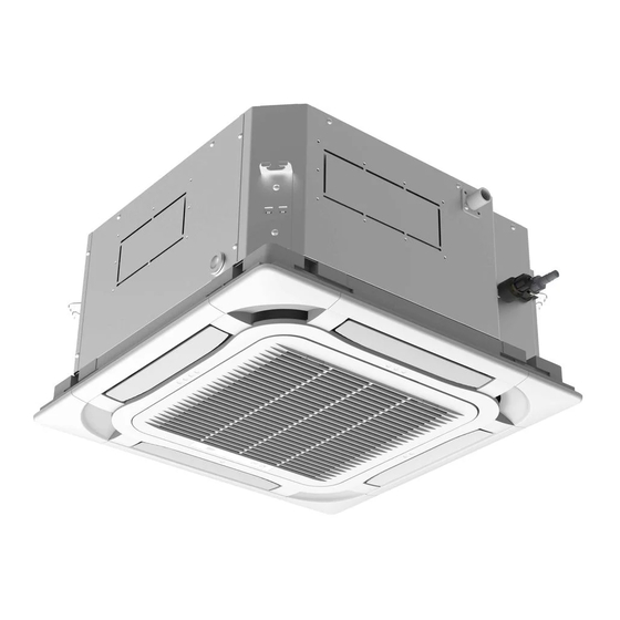
Page 6: Outline Of The Unit And Main Parts
Cassette Type Air Conditioner Unit 2 Outline of the Unit and Main Parts Fig. 2.1... -
Page 7: Preparative For Installation
Cassette Type Air Conditioner Unit 3 Preparative for Installation 3.1 Standard Accessory Parts The standard accessory parts listed below are furnished and should be used as required. Table 3.1 Indoor Unit Accessories Name Appearance Q'ty Usage To connect with the hard PVC Drain Hose drain pipe To fix the hook on the cabinet of... -
Page 8: Selection Of The Installation Location
Cassette Type Air Conditioner Unit Table 3.2 Outdoor Unit Accessories Name Appearance Q'ty Usage Drain Plug 2or3 To plug the unused drain hole. To connect with the hard PVC Drainage Connecter drain pipe 3.2 Selection of the Installation Location WARNING! The unit must be installed where strong enough to withstand the weight of the unit and fixed securely, otherwise the unit would topple or fall off. - Page 9 Cassette Type Air Conditioner Unit fall between the indoor unit and ground is above 1800mm. (7). When installing the suspension bolt, check if the installation place can stand 4 times of the weight of the unit. If not, reinforce it before installation. Note: There will be large amount of greasy dirt accumulated on the fan, heat exchanger and water pump located in the dinning room and kitchen, which would reduce the capacity of the heater exchanger, lead to leakage and abnormal operation of the water pump.
-
Page 10: Connection Pipe Requirement
Item Difference Pipe(Inch) Max. Pipe Length pipe(Outer between Indoor Diameter × wall Model Unit and Outdoor Liquid thickness) (mm) Unit (m) GKH18K3HI φ 26×3 GUHN18NK3HO GKH24K3HI GUHN24NK3HO GKH30K3HI GUHN30NK3HO GKH36K3HI φ 33×4 GUHN36NM3HO GKH42K3HI GUHN42NM3HO GKH48K3HI GUHN48NM3HO GKH60K3HI φ 32×2... -
Page 11: Electrical Requirement
220-240V~ 50Hz Table 3.6 Capability of Air Minimum Sectional Power Supply Fuse Capacity Switch Area Of Earth Wire Outdoor Units V/Ph/Hz GUHN18NK3HO GUHN24NK3HO 220-240V ~ 50Hz GUHN30NK3HO GUHN36NM3HO GUHN42NM3HO 380-415V 3N~50Hz GUHN48NM3HO GUHN60NM3HO Notes: ①. The fuse is located on the main board. -
Page 12: Installation Of The Unit
Cassette Type Air Conditioner Unit they should be modified according to the related national standard. ⑥. Take 2 pieces of power cord of 0.75mm² as the communication lines between indoor and outdoor unit, with their longest lengths of 50 m. Please select the appropriate line length as per the actual installation conditions. - Page 13 Cassette Type Air Conditioner Unit Table 4.1 Unit: mm (inch) Item Model GKH18K3HI For the units: 24k~60k Bottom face of ceiling Fig. 4.2 Table 4.2 Item Model GKH24K3HI GKH30K3HI GKH36K3HI GKH42K3HI GKH48K3HI GKH60K3HI...
- Page 14 Cassette Type Air Conditioner Unit 4.1.2 Installing the Main Body Unit Nut(field supplied) Gas(attachment) Insert Gasket anchor board(attachment) Hoisting stand Tighten(double nuts) [Fix the gasket firmly] [Fix the hoisting stand firmly] One bolt located at one corner of the outlet pipe Center of the ceiling should be fixed on one corner of the drainage slot.
-
Page 15: Installation Of The Outdoor Unit
Cassette Type Air Conditioner Unit φ12.7mm(1/2inch) Fig. 4.4 Fig. 4.5 Fig. 4.6 4.1.4 Leveling The water level test must be done after installing the indoor unit to make the unit is horizontal, as shown below. Horizontal tester Fig. 4.7 4.2 Installation of the Outdoor Unit WARNING ①. - Page 16 Cassette Type Air Conditioner Unit 4.2.1 Outdoor unit dimension Fig. 4.8 Table 4.3 Unit: mm Item Model GUHN18NK3HO GUHN24NK3HO GUHN30NK3HO GUHN36NM3HO GUHN42NM3HO 1120 1100 GUHN48NM3HO 1120 1100 GUHN60NM3HO 1350 4.2.2 Condensate Drainage of the Outdoor Unit Note: Only for the heat pump unit It is required to install a drain pipe for the outdoor unit to drain out the condensate (1).
-
Page 17: Installation Of The Connection Pipe
Cassette Type Air Conditioner Unit Drain cap Bottom Chassis Drain connection Drain pipe mounting hole Fig. 4.9 4.3 Installation of the Connection Pipe 4.3.1 Flare Processing Cut the connection pipe with the pipe cutter and remove the burrs. (1). Hold the pipe downward to prevent cuttings from entering the pipe. (2). - Page 18 Cassette Type Air Conditioner Unit Do not bend the pipes in an angle more than 90° . (2). When pipes are repeatedly bent or stretched, the material will harden, making it (3). difficult to bend or stretch them any more. Do not bend or stretch the pipes more than three times.
- Page 19 Cassette Type Air Conditioner Unit Examine the connection pipe to see if it leaks, then take the treatment of heat insulation, as shown in the Fig. 4.13. Use the medium-sized sponge to insulate the coupler of the gas pipe. Sponge Threaded fastener(×4) Heat insulation sheath (for the liquid tube)
- Page 20 Cassette Type Air Conditioner Unit Gas pipe Liquid pipe Pipe coupling 3-way valve 2-way valve Fig. 4.14 4.3.5 Checking the Pipe Connections for Gas Leaking For both indoor and outdoor unit side, check the joints for gas leaking by the use of a gas leakage detector without fail when the pipes are connected.
-
Page 21: Vacuum And Gas Leakage Inspection
Cassette Type Air Conditioner Unit Fig. 4.16 (2). If the outdoor unit is installed higher than the indoor unit (See Fig. 4.17) 1). Taping should be done from lower to the upper part. 2). All pipes are bound and taped together and also should be trapped to prevent water from returning to the room. - Page 22 Cassette Type Air Conditioner Unit 4.4.1 Vacuum Remove the caps of the liquid valve, gas valve and also the service port. (1). Connect the hose at the low pressure side of the manifold valve assembly to the (2). service port of the unit’s gas valve, and meanwhile the gas and liquid valves should be kept closed in case of refrigerant leak.
-
Page 23: Installation Of The Drain Hose
Cassette Type Air Conditioner Unit Note: For the large-sized unit, it has the service port for both the gas valve and the liquid valve. During evacuation, it is available to connect two hoses of the manifold valve assembly to two service ports to quicken the evacuating speed. - Page 24 Cassette Type Air Conditioner Unit 1/100 so that air may not remain trapped inside the pipe. Keep pipe size equal to or greater than that of the connecting pipe. (2). Install the drain piping as shown and take measures against condensation. (3).
- Page 25 Cassette Type Air Conditioner Unit T-joint converging drain pipes T-joint converging drain pipes Fig. 4.21 When the drain hose cannot keep a sufficient gradient, it is necessary to fit a riser (4). pipe (field supplied) to it. If the air flow of indoor unit is high, this might cause negative pressure and result (5).
- Page 26 Cassette Type Air Conditioner Unit 3-way connection of Connection of drain elbow Connection of horizontal pipe drainage pipe joint Fig. 4.25 Fig. 4.26 Fig. 4.27 4.5.3 Precautions When Doing Riser Piping Work Make sure that heat insulation work is executed on the following 2 spots to (1).
- Page 27 Cassette Type Air Conditioner Unit Fig.4.29 The incline of attached drain hose should be 75 mm or less so that the drain outlet (5). does not have to withstand additional force. Drain hose(attachment) Fig. 4.30 4.5.4 Testing of Drain Piping After piping work is finished, check if drainage flows smoothly.
-
Page 28: The Panel Installation
Cassette Type Air Conditioner Unit 4.6 The Panel Installation 4.6.1 Precautions See the Figure below for the relationship of the front panel and the connecting (1). pipe. Fig. 4.32 Improper screwing of the screws may cause the troubles shown in Fig. 4.33. (2). - Page 29 Cassette Type Air Conditioner Unit Wire the swing flap motor as shown in Fig. 4.35. (4). Connect them to the main body according to the size of terminals Fig. 4.35 4.6.2 Installing the Panel Place the panel at the unit, and latch the hooks beside and opposite the swing flap (1).
-
Page 30: Electrical Wiring
Cassette Type Air Conditioner Unit 4.7 Electrical Wiring 4.7.1 Wiring Precautions WARNING! ①. Before obtaining access to terminals, all supply circuits must be disconnected. ②. The rated voltage of the unit is as shown as Table 3.5 and Table 3.6 ③. - Page 31 Cassette Type Air Conditioner Unit 2). Using a screwdriver, remove the terminal screw (s) on the terminal board. 3). Using a round terminal fastener or pliers, securely clamp a round terminal to each stripped wire end. 4). Position the round terminal wire, and replace and tighten the terminal screw with a screwdriver.(Fig.
- Page 32 Cassette Type Air Conditioner Unit Electric wiring between the indoor and outdoor units (4). Single-phase units18k GUHN18NK3HO+GKH18K3HI ①. Power cord3×2.5mm² (H07RN-F) ②. Power cor3×1.0mm² (H05RN-F) ③. Communication Cords 2×0.75 mm² (H05RN-F) Fig. 4.40 Single-phase units (24~30K) GUHN24NK3HO+GKH24K3HI GUHN30NK3HO+GKH30K3HI ①. Power cord 3×4.0mm² (H07RN-F) ②.
- Page 33 Cassette Type Air Conditioner Unit Three-phase units (60k) GUHN60NM3HO+GKH60K3HI ①. Power cord 5×2.5mm² (H07RN-F) ②. Power cord 3×1.0mm² (H05RN-F) ③. Communication Cords 2×0.75mm² (H05RN-F) Fig. 4.43 Electric wiring of indoor unit side (5). Remove the electric box cover from the electric box sub-assy and then connect the wire.
- Page 34 Cassette Type Air Conditioner Unit ⑦. Connect the indoor unit connection cord properly based on the corresponding marks as shown from Fig. 4.40 to Fig. 4.43. ⑧. Ground both the indoor and outdoor units by attaching a ground wire. ⑨. Unit shall be grounded in compliance with the applicable local and national codes.
-
Page 35: Installation Of Controllers
Cassette Type Air Conditioner Unit Power lines should go along the right side plate and be fixed to the fixation hook with binding wires to keep no contact with pipelines. Communication lines between indoor and outdoor units also should go along the right side plate and keep away from power lines. -
Page 36: Working Temperature Range
Cassette Type Air Conditioner Unit on it. (2). Instructions to the Error Indicating Lamps on the Panel of the Cassette Type Unit. Fig.4.46 Power and ON/OFF Indicating Lamp: It goes red when the unit is powered on while it goes white when the unit is started. ... -
Page 37: Troubleshooting And Maintenance
After carrying out the check of the above items and taking relevant measures to solve the problems but the air-conditioning unit still does not function well, please stop the operation of the unit immediately and contact the local service agency designated by Gree. Only ask professional serviceman to check and repair the unit. -
Page 38: Routine Maintenance
Cassette Type Air Conditioner Unit 7.2 Routine Maintenance Only a qualified service person is allowed to perform maintenance. Disconnect the power supply before cleaning and maintenance. Do not use water or air of 50° C or higher for cleaning air filters and outside panels. Notes: ①. - Page 39 Cassette Type Air Conditioner Unit open panel grille the12k\18k\48k\60k cassette type unit ①. Remove the screws by a screwdriver as Remove the screw shown in the picture. ②. Push those two fasteners and open the Push the fastener panel grille. 2.
- Page 40 GREE ELECTRIC APPLIANCES, INC. OF ZHUHAI Add: West Jinji Rd, Qianshan, Zhuhai, Guangdong, China, 519070 Tel: (+86-756) 8522218 Fax: (+86-756) 8669426 E-mail: gree@gree.com.cn www.gree.com...
Need help?
Do you have a question about the GUHN18NK3HO and is the answer not in the manual?
Questions and answers