Renishaw OLP40 Installation Manual
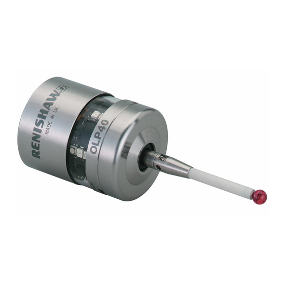
Optical lathe probe
Hide thumbs
Also See for OLP40:
- Quick start manual (92 pages) ,
- Quick start manual (32 pages) ,
- Installation manual (44 pages)
Table of Contents
Advertisement
Quick Links
Advertisement
Table of Contents

Related Manuals for Renishaw OLP40


Summary of Contents for Renishaw OLP40
- Page 1 Installation guide H-5625-8504-05-A OLP40 optical lathe probe...
- Page 2 © 2009-2019 Renishaw plc. All rights reserved. This document may not be copied or reproduced in whole or in part, or transferred to any other media or language, by any means, without the prior written permission of Renishaw plc. The publication of material within this document does not imply freedom from the patent rights of Renishaw plc.
-
Page 3: Table Of Contents
Preparing the OLP40 for use ........ - Page 4 Calibrating the OLP40 ........
-
Page 5: Safety
To reduce the risk of separate collection and disposal of batteries. All shipment delays, if you need to return the OLP40 lithium and rechargeable batteries must be fully to Renishaw for any reason, do not return any discharged or protected from short circuiting prior batteries. - Page 6 It is the machine supplier’s responsibility to ensure that the user is made aware of any hazards OLP40 is ranked Risk Group: Exempt (safe by involved in operation, including those mentioned design). in Renishaw product literature, and to ensure...
-
Page 7: Olp40 Basics
Introduction Getting started Three multicolour probe LEDs provide visual The OLP40 is an optical lathe probe suitable indication of selected probe settings. for use on all sizes of lathes and small multi- tasking machines. It is designed to resist optical For example: interference, false triggering and shock. -
Page 8: Trigger Logic
Trigger Logic review sequence (see page 4.1, “Reviewing the probe settings”, for further information). Probe modes The OLP40 probe can be set in one of three modes: Standby mode – probe is waiting for a switch-on signal. Operational mode – when activated by one of the switch-on methods described later in this section. - Page 9 OLP40 switch-on method OLP40 switch-off method Switch-on time Switch-off options are configurable Optical on Optical off Legacy (start filter off): 0.3 seconds Optical switch-on is commanded by Optical switch-off is commanded by Legacy (start filter on): machine input. machine input. A timer automatically 0.8 seconds...
-
Page 10: Enhanced Trigger Filter
This allows the use of two probes with an OMI-2T Dotted lines on the performance envelopes receiver / interface and up to three probes with represent the OLP40 in low and ultra low optical an OMM-2 receiver with a OSI or OSI-D interface power modes. -
Page 11: Olp40 Dimensions
OLP40 dimensions 19 (0.75) 50 (1.97) Window Battery cassette A range of probe-ready shanks are available from Renishaw M4 stylus 12.5° 12.5° Transmit diode Probe status LED Receive diode 58.3 (2.30) Dimensions given in mm (in) Stylus overtravel limits Stylus length ±X / ±Y... -
Page 12: Olp40 Specification
OLP40 installation guide OLP40 specification Principal application Workpiece inspection and job set-up on all sizes of lathes and small multi-tasking machines. Dimensions Length 58.3 mm (2.30 in) Diameter 40 mm (1.57 in) Weight (without shank) With batteries 277 g (9.77 oz) Without batteries 258 g (9.10 oz) -
Page 13: Typical Battery Life
Typical battery life Modulated transmission 2 × ½AA 3.6 V LTC batteries Standard power Low power Ultra low power (typical) Standby life 600 days 1500 days 1500 days Light usage 1% 460 days 1000 days 1200 days Heavy usage 5% 220 days 480 days 600 days... - Page 14 OLP40 installation guide This page is intentionally left blank.
-
Page 15: System Installation
Section 3, “System installation” System installation Installing the OLP40 with OMM-2 receiver with OSI or OSI-D interface or OMI-2 / OMI-2T / OMI-2H interface / receiver OMI-2 / OMI-2T CNC machine or OMI-2H controller CNC machine OSI or OSI-D OMM-2... -
Page 16: Positioning The Omm-2 Receiver With Osi Or Osi-D Interface Or The Omi-2 / Omi-2T / Omi-2H Interface / Receiver
OMI-2H interface / receiver (modulated OMI-2T / OMI-2H interface / receiver transmission) The diodes of the OLP40 and the OMM-2 receiver WARNING: Ensure the machine tool is in a safe / OMI-2 / OMI-2T / OMI-2H interface / receiver condition and power is removed before removing must be in each other’s field of view and within... -
Page 17: Preparing The Olp40 For Use
Preparing the OLP40 for use Fitting the stylus 1.8 Nm – 2.2 Nm (1.3 lbf.ft – 1.6 lbf.ft) M-5000-3707... -
Page 18: Stylus Weak Link
OLP40 installation guide Stylus weak link NOTE: Steel styli must be used for optimum 1.8 Nm – 2.2 Nm metrology performance. Do not use a weak link (1.3 lbf.ft – 1.6 lbf.ft) with ceramic or carbon fibre styli. Fitting a stylus with a weak link onto the... -
Page 19: Installing The Batteries
Installing the batteries NOTES: See page 5.2, “Changing the batteries”, for a list of suitable battery types. If dead batteries are inadvertently inserted, the LEDs will remain a constant red. Do not allow coolant or debris to enter the battery compartment. -
Page 20: Mounting The Probe On A Shank
OLP40 installation guide Mounting the probe on a shank × 2 2 mm A/F × 2 2 mm A/F × 4 × 4 2 mm A/F × 2 0.5 Nm – 1.5 Nm (0.4 lbf.ft – 1.1 lbf.ft) -
Page 21: Stylus On-Centre Adjustment
Stylus on-centre adjustment Adjust in X axis NOTES: If a probe and shank assembly is dropped, it must be rechecked for correct on-centre adjustment. < ±20 μm Do not hit or tap the probe to achieve on-centre adjustment. × 4 × 4 Adjust in Y axis ×... -
Page 22: Stylus Trigger Force And Adjustment
Spring force within the probe causes the stylus to sit in a unique position and return to this position following each stylus deflection. Stylus trigger force is set by Renishaw. The 2 mm A/F user should only adjust trigger force in special... -
Page 23: Calibrating The Olp40
Calibrating the OLP40 Three different operations are to be used when calibrating a probe. They are: Why calibrate a probe? • calibrating either in a bored hole or on a turned diameter of known position; An inspection probe is just one component of the measurement system which communicates •... - Page 24 OLP40 installation guide 3.10 This page is intentionally left blank.
-
Page 25: Reviewing The Probe Settings
Section 4, “Trigger Logic™” Trigger Logic™ Reviewing the probe settings LED check > 5 s Key to the symbols LED short flash × LED long flash Switch-off method Optical off Short timeout Medium timeout Long timeout 12 s 33 s 134 s Enhanced trigger filter 0 ms... -
Page 26: Probe Settings Record
On (10 ms) Optical transmission Legacy (start filter off) method Legacy (start filter on) Modulated PROBE 1 Modulated PROBE 2 Modulated PROBE 3 Optical power Standard Ultra low Factory settings are for kit A-5625-2001 only. OLP40 serial no ........ - Page 27 This page is intentionally left blank.
-
Page 28: Changing The Probe Settings
OLP40 installation guide Changing the probe settings Insert the batteries or, if they have already been > 5 s installed, remove them for five seconds and then refit them. Following the LED check, immediately deflect the stylus and hold it deflected until eight red flashes have been observed (if the battery power is low, each red flash will be followed by a blue flash). - Page 29 Optical power Standard Ultra low Return to “Switch-off method” New settings complete...
-
Page 30: Master Reset Function
Master reset function To reset the probe Insert the batteries or, if they have already OLP40 features a master reset function to assist been installed, remove them for five seconds users who have mistakenly changed the probe and then refit them. - Page 31 Switch-off method Optical off Short timeout Medium timeout Long timeout 12 s 33 s 134 s × Deflect the stylus for 20 seconds until the status LEDs start to flash yellow eight times. Whilst the status LEDs are flashing yellow to confirm that a master reset is required, release the stylus and then hold the stylus deflected again until the eight yellow flash sequence has ended.
-
Page 32: Operating Mode
OLP40 installation guide Operating mode LEDs LEDs LEDs flashing flashing flashing green Probe status LEDs LED colour Probe status Graphic hint Flashing green Probe seated in operating mode Flashing red Probe triggered in operating mode Flashing green and blue Probe seated in operating mode – low battery Flashing red and blue Probe triggered in operating mode –... -
Page 33: Maintenance
Further dismantling and repair of Renishaw transmission. equipment is a highly specialised operation, which must be carried out at an authorised Renishaw Service Centre. Equipment requiring repair, overhaul or attention under warranty should be returned to your supplier. -
Page 34: Changing The Batteries
OLP40 installation guide Changing the batteries CAUTIONS: Do not leave dead batteries in the probe. When changing batteries, do not allow coolant or debris to enter the battery compartment. When changing batteries, check that the battery polarity is correct. Take care to avoid damaging the battery cassette gasket. - Page 35 NOTES: After removing the old batteries, wait more than 5 seconds before inserting the new batteries. Do not mix new and used batteries or battery types, as this will result in reduced life and damage to the batteries. Always ensure that the cassette gasket and mating surfaces are clean and free from dirt before reassembly.
-
Page 36: Olp40 Eyelid
OLP40 installation guide OLP40 eyelid CAUTION: Do not use a sharp tool or a The OLP40 is fitted with a metal eyelid that degreasing agent. protects the internal components of the probe from hot chip and coolant environment. Dirt may... -
Page 37: Fault-Finding
Optical/magnetic interference. Check for interfering lights or motors. Transmission beam obstructed. Check that the OLP40 and receiver windows are clean and remove any obstruction. No receiver start signal. Check start signal by reviewing receiver start LED. - Page 38 OLP40 installation guide Symptom Cause Action Machine stops Optical communication obstructed. Check interface / receiver and unexpectedly during a remove obstruction. probing cycle. Interface / receiver / machine fault. Refer to interface / receiver / machine user’s guide. Dead batteries.
- Page 39 Symptom Cause Action Poor probe repeatability Debris on part or stylus. Clean part and stylus. and/or accuracy. Poor tool change repeatability. Redatum probe after each tool change. Loose probe mounting on shank Check and tighten as appropriate. or loose stylus. Excessive machine vibration.
- Page 40 OLP40 installation guide Symptom Cause Action Probe fails to switch off. Incorrect “switch-off” method Reconfigure to optical off mode. configured. Optical/magnetic interference. Check for interfering lights or motors. Consider removing the interfering source. Probe is inadvertently switched Check position of receiver.
-
Page 41: Parts List
Item Part number Description OLP40 A-5625-2001 OLP40 probe with batteries, tool kit and quick-start guide (set to optical on / optical off) – modulated transmission, PROBE 1 start. OLP40 A-5625-2002 OLP40 probe with batteries, tool kit and quick-start guide (set to optical on / time off 134 sec) –... - Page 42 OLP40 installation guide Item Part number Description Publications. These can be downloaded from our website at www.renishaw.com. OLP40 QSG H-5625-8500 Quick-start guide: for rapid set-up of the OLP40 probe. OMI-2 QSG H-5191-8500 Quick-start guide: for rapid set-up of the OMI-2.
-
Page 43: General Information
Trade marks exclusions from the warranty are if the equipment has been: RENISHAW and the probe symbol used in the RENISHAW logo are registered trade marks of • neglected, mishandled or inappropriately used;... -
Page 44: Patents
OLP40 installation guide Patents Microchip software licensing agreement Features of the OLP40, and other similar Renishaw products, are the subject of one or This product’s firmware has been developed by more of the following patents and/or patent Renishaw with the use of the Microchip libraries,... -
Page 45: Eu Declaration Of Conformity
47 CFR Section 15.19 Renishaw plc declares under its sole responsibility This device complies with part 15 of the FCC that the OLP40 is in conformity with all relevant Rules. Operation is subject to the following two Union legislation. conditions:... - Page 46 Renishaw plc +44 (0) 1453 524524 +44 (0) 1453 524901 New Mills, Wotton-under-Edge uk@renishaw.com Gloucestershire, GL12 8JR www.renishaw.com United Kingdom For worldwide contact details, visit www.renishaw.com/contact *H-5625-8504-05* Issued: 10.2019 Part no. H-5625-8504-05-A © 2010–2019 Renishaw plc...
Need help?
Do you have a question about the OLP40 and is the answer not in the manual?
Questions and answers