Table of Contents
Advertisement
OPERATOR MANUAL
& PARTS CATALOG
143351 v1.3
JOHN DEERE
D E G E L M A N
I N D U S T R I E S
L T D.
B O X
8 3 0 - 2 7 2
I N D U S T R I A L
D R I V E ,
9R SERIES - FT4
R E G I N A ,
S K ,
C A N A D A ,
S 4 P
3 B 1
F A X 3 0 6 . 5 4 3 . 2 1 4 0
P H 3 0 6 . 5 4 3 . 4 4 4 7
9370R, 9420R, 9470R, 9520R, 9570R, 9620R
1 . 8 0 0 . 6 6 7 . 3 5 4 5
D E G E L M A N . C O M
Advertisement
Table of Contents

Related Manuals for Degelman 6900 Series


Summary of Contents for Degelman 6900 Series
- Page 1 OPERATOR MANUAL & PARTS CATALOG 143351 v1.3 JOHN DEERE D E G E L M A N I N D U S T R I E S L T D. B O X 8 3 0 - 2 7 2 I N D U S T R I A L D R I V E , 9R SERIES - FT4...
- Page 3 QUICK GUIDE INDEX Introduction Safety Operation Maintenance Transport & Storage Troubleshooting Blade Attachments Blade Components Pivot & Main Frame Mounting Brackets Single Reduction (SR) Axle Models Double Reduction Axle Models with HydraCushion™ Suspension (HC) Double Reduction (DR) Axle Models Mounting Brackets - Optional Mounts Cylinders Hydraulic Routing Mounting Procedure...
-
Page 5: Proof Of Ownership
Introduction WELCOME PROOF OF OWNERSHIP Degelman is proud to welcome you to our rapidly Serial Number Plate increasing family of high quality and dependable product owners. This product was designed and built specifically for you, the customer. Through our research and with your input and feedback, we present to you our 69/7200 Series Dozer Blades. -
Page 6: Safety Alert Symbol
YOU are responsible for the SAFE operation and SAFETY ALERT SYMBOL maintenance of your Degelman implement. YOU must ensure that you and anyone else who is going to operate, maintain, or work around the machine be familiar with the operating and maintenance procedures, and related SAFETY information contained in this manual. -
Page 7: General Safety
Safety GENERAL SAFETY 1. Read and understand the Operator's Manual Wear Protective Equipment and all safety signs before using. Review safety Note: Before working on machine, always turn related items with all operators annually. tractor off, set controls in neutral, and remove ignition key. -
Page 8: Operation
Operation TO THE NEW OPERATOR OR OWNER TRACTOR PREPARATION The Degelman Dozer Blade is a push type tractor 1. Wheel Spacing attachment designed primarily for excavating, levelling and filling of dirt, snow and silage. Important: To avoid possible damage from... -
Page 9: Operator's Responsibility
Operation OPERATOR’S RESPONSIBILITY BLADE DEPTH Every operator should read this manual and Gauge the depth of cut to push the most material be instructed in safe operating procedures. An possible without losing speed through spinning untrained operator is not qualified to operate this the wheels or slowing the tractor engine. -
Page 10: Maintenance Safety
Maintenance LUBE AFTER EVERY 8 HRS. MAINTENANCE SAFETY 1. Review the Operator’s Manual and all safety items before working with, maintaining or Items to Grease Qty. operating the machine. Angle Cylinder Pins 2 per cylinder Lift Cylinder Pins 2 per cylinder 2. -
Page 11: Hydraulic Safety
Maintenance HYDRAULIC SAFETY HARDWARE TORQUE SETTINGS 1. Always place all tractor hydraulic controls in The tables below give correct torque values for various neutral before dismounting. bolts and capscrews. Tighten all bolts to values in charts unless otherwise noted. Check tightness of bolts 2. - Page 12 Maintenance HYDRAULIC CYLINDER REPAIR 5. Take the plastic removal ring from the seal kit: PREPARATION Types of Cylinders a) Straighten the ring and remove any kinks or When cylinder repair (Wire Ring / Threaded Head) excessive curl to make installation easier and is required, clean off prevent it from falling out.
- Page 13 Maintenance 8. Remove locknut, piston and head from rod. 11. b) Tighten the band clamp to ensure the wire ring is fully seated. Then, loosen the clamp Piston Seal (2pcs) approx. 1/2 a turn to allow band clamp to slide Wear Ring during final assembly.
- Page 14 Maintenance REPAIRING A THREADED HEAD CYLINDER REPAIRING A THREADED HEAD CYLINDER SET SCREW Locking Ring Style STYLE Barrel Barrel Locking Set Screw Gland Ring Lock Piston U-Cup Wear Dual Seal Seal Piston O-Rings Ring Piston Seals Seal Wiper (Style may vary, Seal Lock Wear Ring...
- Page 15 • Store unit in an area away from human activity. 142279 Amber Reflector, 3-1/4” lg • Do not permit children to play near the stored unit. Product Decals 142008 Degelman Logo, 25-3/4” lg 142908 7200 Blade Decal 142907 6900 Blade Decal 143351 - 69/7200 Series...
-
Page 16: General Troubleshooting
Troubleshooting GENERAL TROUBLESHOOTING SYMPTOM PROBLEM SOLUTION Blade falls down in Lift cylinder hydraulic circuit not connected Trace your hoses from front to back of tractor, making sure angle transport. correctly. circuit connected to rear relief valve, not lift circuit. Blade angle won’t Excessive loading of dozer. -
Page 17: Blade Attachments
Blade Attachments OPTIONAL BLADE ATTACHMENTS Silage Extension 112852 - 16 ft (shown) 112851 - 14 ft 112850 - 12 ft Silage Extension Hardware 118410 - Nut, 3/4” (8) 118509 - Lock Washer, 3/4” (8) 118516 - Flat Washer, 3/4” (16) Top Extension 118047 - Bolt, 3/4”x 2-1/2”... -
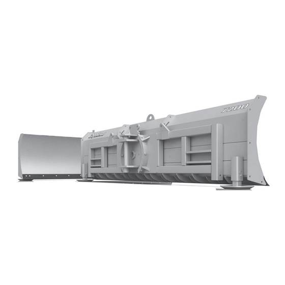
Page 18: Blade Components
Blade Components 69/7200 PIVOT PIN 6900 Series Dozer Blades 112274 - Pivot Pin (1) 112362 - 16 ft 112361 - 14 ft (shown) 118048 - Bolt, 3/4” x 112360 - 12 ft 2-1/2” UNC GR8 (2) 118775 - Flat Washer, 3/4”... - Page 19 Pivot & Main Frame PIVOT & MAIN FRAME OVERVIEW PIVOT & MAIN FRAME COMPONENTS 123082 - Cylinder, 4-1/2 x 20 x 2 (2) Previously: 123470 - Cylinder (2) 117145 - Bushing (2) 791200 - Main Frame Assembly (1) 117413 - Bolt, 5/16 118121 - Bolt, x 3-3/4 (2) 5/16 x 2 (2)
- Page 20 Mounting Brackets - Single Reduction (SR) UNDER CARRIAGE BRACKET LOCATIONS SINGLE REDUCTION (SR) AXLE MODELS If installed, remove Toolbox (Front Left), Tow Cable Attachment Bracket (Front Right), and Front Weight Stack Components mounting bracket. IMPORTANT NO GAPS! * Use Shims only as required to ensure “No-Gap”...
- Page 21 Mounting Brackets - Single Reduction (SR) UNDER CARRIAGE BRACKET LOCATIONS SINGLE REDUCTION (SR) AXLE MODELS If installed, remove Toolbox (Front Left), Tow Cable Attachment Bracket (Front Right), and Front Weight Stack Components mounting bracket. IMPORTANT NO GAPS! * Use Shims only as required to ensure “No-Gap”...
- Page 22 Mounting Brackets - HydraCushion Suspension (HC) UNDER CARRIAGE BRACKET LOCATIONS DOUBLE REDUCTION AXLE MODELS with HydraCushion™ Suspension (HC) If installed, remove Toolbox (Front Left), Tow Cable Attachment Bracket (Front Right), and Front Weight Stack Components mounting bracket. IMPORTANT NO GAPS! * Use Shims only as required to IMPORTANT-TORQUE...
- Page 23 Mounting Brackets - HydraCushion Suspension (HC) UNDER CARRIAGE BRACKET LOCATIONS DOUBLE REDUCTION AXLE MODELS with HydraCushion™ Suspension (HC) If installed, remove Toolbox (Front Left), Tow Cable Attachment Bracket (Front Right), and Front Weight Stack Components mounting bracket. IMPORTANT NO GAPS! * Use Shims only as required to IMPORTANT-TORQUE...
- Page 24 Mounting Brackets - Double Reduction (DR) UNDER CARRIAGE BRACKET LOCATIONS DOUBLE REDUCTION (DR) AXLE MODELS (without HydraCushion™) If installed, remove Toolbox (Front Left), Tow Cable Attachment Bracket (Front Right), and Front Weight Stack Components mounting bracket. IMPORTANT NO GAPS! * Use Shims only as required to ensure “No-Gap”...
-
Page 25: Mounting Brackets
Mounting Brackets OPTIONAL KITS TOOLBOX, TOW CABLE, & EURO LIGHT RELOCATION KITS - Front tractor bumper (R296504) needs to be removed prior to installation of the “Tow Cable Relocation Kit”. - The “Toolbox or Euro Light Relocation Kits” do not require removal of the front bumper, but it could aid in installation. - Page 26 Cylinders TILT CYLINDERS 123196 - Cylinder, 4” x 8” x 2” PREVIOUS: 122734 - Cylinder, 4” x 8” x 2” 121796 - Barrel (1) 118946 - Lock nut, 1-1/4” UNF GR5 122783 - Lock Ring (1) unitorque (1) 122781 - Open Cap (1) 122774 - Piston (1) 123079 - Seal Kit 122775 - Rod &...
-
Page 27: Hydraulic Routing
Hydraulic Routing HYDRAULIC & COUPLER MOUNTING BRACKETS 118718 - Lock Nut, 5/16 (4) 141674 - Flush Face Quick 118731 - Flat Washer, 5/16 (8) Coupler-m (4 or 6) 118110 - Bolt, 5/16 x 1 (4) 141618 - Nipple, 3/4 JIC-m x 1-1/16 789722 - Hydraulic Coupler ORB (4 or 6) Bracket (1) - Page 28 Hydraulic Routing TILT CYLINDER ROUTING 7200 Models Only 123196 - Cylinder, 4 x 8 x 2 (2) Previously: 122734 - Cylinder (2) 126690 - Hose, 1/2 x 25 (2) 126572 - Hose, 1/2 x 169 (2) 141504 - 90° Elbow, 3/4 JIC-m x ORB (2) 141527 - Tee, 3/4 JIC-m x JIC-m x ORB (2) 141518 - 90°...
- Page 29 Hydraulic Routing FRONT HYDRAULIC CONNECTION DETAIL BALL VALVE ROUTING Front of 126566 - Hose, 1/2 x 75 From Front Cylinders Tractor 126610 - Hose, 1/2 x 311 (1) From Angle Cylinders Hoses from 141515 - Connector, front cylinders From Lift Cylinders 3/4 JIC-m x ORB (1) are wrapped From Rear...
- Page 30 Hydraulic Routing REAR HOSE ROUTING Refer to Front Hydraulic Connection Details 126597 - Hose, 1/2 x 52 (3) Note: 7200 Models require 126513 - Hose, 1/2 x 264 (2) extra hoses for Tilt System. 126610 - Hose, 1/2 x 311 (2 or 4) 141504 - 90°...
- Page 31 Mounting HYDRAULIC QUICK-TACH 10 STEP MOUNTING PROCEDURE Please note: The brackets and frame Procedure to mount blade: assembly for your particular fit-up may 1. Align the tractor behind the main frame. differ significantly from those used in the (Unhook & lower front Tow Cable - if applicable) diagram, however, the basic mounting procedure should remain the same.
- Page 32 2. To any goods that have sustained damage or deterioration attributable to a lack of routine maintenance (eg. Re- torque of mounting hardware.) 3. If parts not made or supplied by Degelman have been used in the connection with the unit, if, in the sole judgement of Degelman such use affects its performance, safety, stability or reliability.
Need help?
Do you have a question about the 6900 Series and is the answer not in the manual?
Questions and answers