FMI VLDV43NE Operation And Installation Manual
Direct vent fireplace
Hide thumbs
Also See for VLDV43NE:
- Owner's operation and installation manual (44 pages) ,
- Owner's operation and installation manual (40 pages) ,
- Owner's operation and installation manual (44 pages)
Table of Contents

Related Manuals for FMI VLDV43NE


Summary of Contents for FMI VLDV43NE
- Page 1 DIRECT VENT FIREPLACE OWNER’S OPERATION AND INSTALLATION MANUAL ® MODELS (V)LDV43NE AND (V)LDV43PE WARNING: If the information in this manual is not — WHAT TO DO IF YOU SMELL GAS For more information, visit www.fmiproducts.com...
-
Page 2: Table Of Contents
TABLE OF CONTENTS Safety ..............2 Inspecting Burners..........25 Local Codes............4 Gas Control Module System......26 ........... 5 Cleaning and Maintenance........ 30 Product Features ..........5 ............ 31 Pre-installation............. 6 Replacement Parts ..........31 Location of Termination Cap........ 8 Technical Service.......... -
Page 3: Safety
SAFETY Continued FMI PRODUCTS, LLC vent pipe components and terminations. National Safety Standards and is listed and tested by PFS Cor- poration to ANSI Z21.88/CSA 2.33 standard as WARNING: Do not allow fans in fresh air for combustion through the outer pipe and combustion gases are exhausted through the inner pipe. -
Page 4: Local Codes
SAFETY Continued 6. Have venting system inspected annually structure. Locate propane/LP supply have venting system cleaned or repaired. See Cleaning and Maintenance, page 30. problems, do not use propane/LP fuel tank 7. Do not use any solid fuels (wood, coal, of less than 100 lb. -
Page 5: Product Features
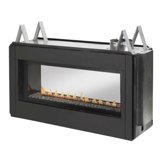
PRODUCT IDENTIFICATION Spacers Glass Door Flue Collar Nailing Flange Pebble Pan Access Door Figure 1 - Direct Vent Linear Fireplace PRODUCT FEATURES These are a few facts that can help you under- may notice some amount of condensation is normal and will disappear after 10-20 outside of your home in several ways. - Page 6 REQUIREMENTS FOR THE COMMONWEALTH OF MASSACHUSETTS For all side wall horizontally vented gas fueled INSPECTION equipment installed in every dwelling, building or The state or local gas inspector of the side structure used in whole or in part for residential wall horizontally vented gas fueled equipment purposes, including those owned or operated by shall not approve the installation unless, upon...
-
Page 7: Pre-Installation
PRE-INSTALLATION LOCATION AND SPACE CLEARANCES REQUIREMENTS Minimum clearances to combustibles for the *Back and sides 1" Perpendicular walls 8" that rafters and wall studs are not in the way of the venting system. Choose a location where the heat output is not affected by drafts, 63"... - Page 8 PRE-INSTALLATION Continued 17.50" Concrete Board 38" 53.25" Figure 4 - Installing Concrete Board Figure 2 - Framing Clearances for One Sided Application Wall 15.25" 38" Mantel Mantel from 12" 24" 9" 21" 6" 18" 4" 16" 2" 14" 53.25" Figure 3 - Framing Clearances for See- Thru Application SAFE 4"...
- Page 9 PRE-INSTALLATION Continued Figure 6 - (V)LDV43 Series Dimensions www.fmiproducts.com 125898-01A...
-
Page 10: Location Of Termination Cap
LOCATION OF TERMINATION CAP Fixed Openable Fixed Closed Closed Openable TERMINATION CAP GAS METER RESTRICTED AREA AIR SUPPLY INLET (TERMINATION PROHIBITED) I = clearance to service regulator vent outlet [*72" (182.9 cm) A = clearance above grade, veranda, porch, deck, or balcony [*12"... -
Page 11: Venting Installation
FMI tally on an outside wall, you may install PRODUCTS, LLC a standoff if the termination cap is to be these instructions such as vinyl, wood, stucco, etc. - Page 12 VENTING INSTALLATION Continued INSTALLATION PLANNING etrated is constructed of noncombustible material, such as masonry block or con- There are two basic types of direct vent crete, a 8 " hole with zero clearance is installation: WARNING: Do not recess Horizontal Termination Installation IMPORTANT: Horizontal square terminations zontal installations using round termination Female...
- Page 13 VENTING INSTALLATION Continued Position sembly attached, toward wall and insert horizontal vent cap in center of the 8 " vent pipe into horizontal termination. Pipe round hole and attach to exterior wall overlap should be a minimum of 1 " (see with four wood screws provided.
- Page 14 VENTING INSTALLATION Continued GROUND FLOOR INSTALLATION Minimum Siding Recommended Applications: Pipe Standoff Overlap Direct Screws termination Vent Pipe 1' Pipe Min On Wall 90° Elbow Horizontal Run Firestop Wall V + 90· Elbow Firestop Maintain 1" Minimum Air Space Around Horizontal High High Wind Outer Pipe When...
- Page 15 VENTING INSTALLATION Continued 3. Cut a hole in the roof using locating hole as a center point. (Cover any exposed plumb line down from ceiling to position open vent pipes before cutting hole in " x 11 " hole must be where vent will penetrate ceiling.
- Page 16 VENTING INSTALLATION Continued 6. Continue to add pipe sections until height 7. Twist-lock vent cap onto last section of of vent cap meets the minimum building vent pipe. code requirements described in Figure 6 Note: If vent pipe passes through any occupied ar- on page 10.
-
Page 17: Fireplace Installation
FIREPLACE INSTALLATION For propane/LP connection only, the installer must supply an external regulator. The exter- nal regulator will reduce incoming gas pres- sure. You must reduce incoming gas pressure to between 11" and 14" of w.c. pressure. If according to your gas type. you do not reduce incoming gas pressure, INSTALLING GAS PIPING TO external regulator with the vent pointing down... - Page 18 FIREPLACE INSTALLATION Continued Check your building codes for any special requirements for locating equipment shutoff threads. This will prevent excess sealant from going into pipe. Excess sealant in pipe could We recommend that you install a sediment trap/drip leg in supply line as shown in Figure 19.
- Page 19 FIREPLACE INSTALLATION Continued tank or gas meter to equipment shutoff and connections, internal and external to unit, for leaks after 4. Correct all leaks at once. Equipment Open Shutoff Valve WARNING: Never use an Closed Figure 21 - Equipment Shutoff Valve Equipment Shutoff Valve PRESSURE TESTING GAS SUPPLY...
- Page 20 FIREPLACE INSTALLATION Continued the OFF position. DOOR valve to gas valve (see Figure 22 or forming show a leak. Correct all leaks at once. Operation see Parts To Turn Off Gas to Appliance FINISHING FIREPLACE FOR INSTALLATION panel semi-installed. If you will be using the place to a see-thru, the rear panel will need to be removed (See Upgrading (V)LDV43 Series to See-Thru Application...
- Page 21 FIREPLACE INSTALLATION Continued slots by using too much ember material in one area. Do not block pilot ports with opening tilting top of door about 45° to- embers. It is not necessary to use all of the glowing ember material provided. door into the retaining channel at the APPLICATION 3.
- Page 22 FIREPLACE INSTALLATION Continued glass door. Refer to Removing/Replacing Glass Door, page 20 of this manual for instruction. Discard false door. Refer to Removing/Replacing Glass Door, page 20 of this manual when removing glass door. 3. Remove 2 side walls and then the rear Retaining wall.
- Page 23 FIREPLACE INSTALLATION Continued Side You may chose to drill pilot holes into the Access Filler face using a 1/8" drill bit. Do not use self Door tapping screws, use any #10 x 1/2" screw. 3. In locations of extreme weather, it is rec- ommended to apply a bead of high tem- perature sealant around the edge where NOTE:...
-
Page 24: Operation
FIREPLACE INSTALLATION Continued Trim the top and bottom trim pieces as shown in Figure 35. 2. Remove 8 screws at top and bottom of glass door and remove glass door. Screws Trim Figure 35 - Removing Exterior Glass Door for Cleaning OPERATION FOR YOUR SAFETY LIGHTING... -
Page 25: Inspecting Burners
10. Turn safety shutoff switch to the ON TO TURN OFF GAS position. TO APPLIANCE 11. Visually locate pilot. Ignitor should begin 1. Turn off safety shutoff switch. to spark and main burner should ignite 2. Turn off all electric power to appliance if service is to be performed. -
Page 26: Gas Control Module System
GAS CONTROL MODULE SYSTEM The module has 2 special features built into 3. When the remote/off is in the REMOTE the system. position the burner will operate from the Remote Control transmitter. Continuous Pilot Feature This allows the change from a spark to pilot NOTE: The module must be programmed to system to a standing pilot system the Remote Control transmitter. - Page 27 GAS CONTROL MODULE SYSTEM Continued Manual Mode Continuous Pilot Push MODE button for manual ON, the Operation of this feature of having the pilot to run all the time will be activated with the The second push of the MODE button will pressing of two buttons, "PROG/TIME"...
- Page 28 GAS CONTROL MODULE SYSTEM Continued Pushing "TIMER" button, you can set the clock area. burner, that is controlled with a step motor on the gas valve. You can press the "up" or the "down" to set your desired TIMER segment. ing information from the handheld control.
- Page 29 GAS CONTROL MODULE SYSTEM Continued Following is the set up for the Program Mode: Push & hold button for more than 2 seconds to enter the setting for program mode: & SET button to enter into next setting. ON". Then you push SET button to enter PROGRAM setting will only last for 2 Min- into next setting.
-
Page 30: Cleaning And Maintenance
CLEANING AND MAINTENANCE Replacement Parts, If glass has been broken, carefully remove GLASS DOORS glass door (see Removing/Replacing Glass Door a shop vac. CAUTION: Do not vacuum if Use only glass door replacement intended for Replacement Parts, page WARNING: Do not use may be made. -
Page 31: Replacement Parts
SERVICE HINTS You may have further questions about When Gas Pressure Is Too Low installation, operation, or troubleshooting. If so, contact FMI PRODUCTS, LLC at 1-866-328-4537. When calling please have your model and serial numbers of your heater ready. You can also visit our web site at You may feel your gas pressure is too low. -
Page 32: Troubleshooting
TROUBLESHOOTING Note: All troubleshooting items are listed in order of operation. POSSIBLE CAUSE REMEDY Pilot will not light 1. No gas supply or shutoff 1. Check to see if you have gas valve is OFF supply and that equipment shutoff valve is opened 2. - Page 33 TROUBLESHOOTING Continued POSSIBLE CAUSE REMEDY Pilot will not stay lit 1. Loose wiring on ignitor wire to ignition module and/ the "I" wire are properly or poor ground to ignition connected to the module module in the proper "S" and "I" spark to the pilot burner is properly grounded to the gas control valve and to the...
- Page 34 TROUBLESHOOTING Continued POSSIBLE CAUSE REMEDY Gas odor even when gas 1. Gas leak. 1. Locate and correct all leaks control valve is off (see Checking Gas Con- nections 2. Control valve defective 2. Replace control valve Gas odor during combustion 1.
-
Page 35: Wiring Diagram
WIRING DIAGRAM www.fmiproducts.com 125898-01A... -
Page 36: Parts
PARTS www.fmiproducts.com 125898-01A... - Page 37 PARTS instructions listed under Replacement Parts on page 31 of this manual. DESCRIPTION 125609-02 Pilot Bracket 125699-01 Pilot, NG 125699-02 Pilot, LP 125752-01 Burner Assembly 125961-01 Light Assembly w/ Wire Harness 25599 23106 14296 Brass Elbow 114027-01 Grommet 116573-01 Flat Washer 11214 Bulkhead Fitting 14399...
- Page 38 PARTS www.fmiproducts.com 125898-01A...
-
Page 39: Accessories
Purchase these accessories from your local dealer. If they can not supply these accessories LDSTI call FMI PRODUCTS, LLC at 1-866-328-4537 for information. You can also write to the ad- dress listed on the back page of this manual. LDSTO... -
Page 40: Warranty
FMI PRODUCTS, LLC’s liability is limited to the purchase price of the product, and FMI PRODUCTS, LLC shall not be liable for any other damages whatsoever under any circumstances including indirect, incidental, or consequential damages.
Need help?
Do you have a question about the VLDV43NE and is the answer not in the manual?
Questions and answers