FMI LDV43Ne Owner's Operation And Installation Manual
Direct vent
Hide thumbs
Also See for LDV43Ne:
- Owner's operation and installation manual (44 pages) ,
- Owner's operation and installation manual (44 pages) ,
- Operation and installation manual (40 pages)
Table of Contents
Advertisement
Quick Links
PFS
C
MODELS (V)LDV43NE AND (V)LDV43PE
WARNING: If the information in this manual is not
followed exactly, a fire or explosion may result causing
property damage, personal injury or loss of life.
— Do not store or use gasoline or other flammable
vapors and liquids in the vicinity of this or any other
appliance.
— WHAT TO DO IF YOU SMELL GAS
• Do not try to light any appliance.
• Do not touch any electrical switch; do not use any
phone in your building.
• Immediately call your gas supplier from a neighbor's
phone. Follow the gas supplier's instructions.
• If you cannot reach your gas supplier, call the fire
department.
— Installation and service must be performed by a quali-
fied installer, service agency or the gas supplier.
INSTALLER: Leave this manual with the appliance
CONSUMER: Retain this manual for future reference.
For more information, visit www.fmiproducts.com
®
US
DIRECT VENT
FIREPLACE
OWNER'S OPERATION AND
INSTALLATION MANUAL
Advertisement
Table of Contents

Related Manuals for FMI LDV43Ne


Summary of Contents for FMI LDV43Ne
-
Page 1: Direct Vent
FIREPLACE OWNER’S OPERATION AND INSTALLATION MANUAL ® MODELS (V)LDV43NE AND (V)LDV43PE WARNING: If the information in this manual is not followed exactly, a fire or explosion may result causing property damage, personal injury or loss of life. — Do not store or use gasoline or other flammable vapors and liquids in the vicinity of this or any other appliance. -
Page 2: Table Of Contents
TABLE OF CONTENTS Safety ..............2 Inspecting Burners..........25 Local Codes............4 Gas Control Module System......26 Product Identification ........... 5 Cleaning and Maintenance ........ 30 Product Features ..........5 Specifications ............ 31 Pre-installation ............. 6 Replacement Parts ..........31 Location of Termination Cap ........ -
Page 3: Safety
This fireplace must be installed with FMI PRODUCTS, LLC vent pipe components gas indicated on the rating plate. and terminations. This appliance is not convertible... -
Page 4: Local Codes
SAFETY Continued 1. For propane/LP fireplace, do not place 6. Have venting system inspected annually propane/LP supply tank(s) inside any by a qualified service person. If needed, structure. Locate propane/LP supply have venting system cleaned or repaired. tank(s) outdoors. To prevent performance See Cleaning and Maintenance, page 30. -
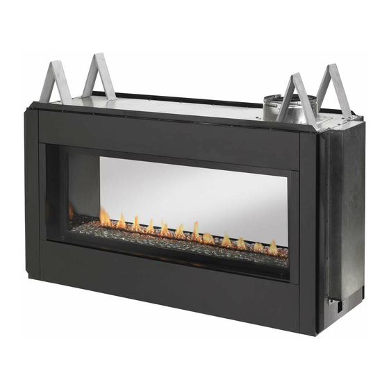
Page 5: Product Identification
PRODUCT IDENTIFICATION Spacers Glass Door Flue Collar Nailing Flange Pebble Pan Access Door Figure 1 - Direct Vent Linear Fireplace PRODUCT FEATURES These are a few facts that can help you under- • Each time you turn on your fireplace, you stand and enjoy your direct vent fireplace: may notice some amount of condensation on the inside of the fireplace glass. - Page 6 REQUIREMENTS FOR THE COMMONWEALTH OF MASSACHUSETTS INSPECTION For all side wall horizontally vented gas fueled equipment installed in every dwelling, building or The state or local gas inspector of the side structure used in whole or in part for residential wall horizontally vented gas fueled equipment purposes, including those owned or operated by shall not approve the installation unless, upon...
-
Page 7: Pre-Installation
PRE-INSTALLATION LOCATION AND SPACE CLEARANCES REQUIREMENTS Minimum clearances to combustibles for the fireplace are as follows: Determine the safest and most efficient loca- *Back and sides 1" tion for your direct vent fireplace. Make sure that rafters and wall studs are not in the way Perpendicular walls 8"... - Page 8 PRE-INSTALLATION Continued 17.50" Concrete Board 38" 53.25" Figure 4 - Installing Concrete Board Figure 2 - Framing Clearances for One Sided Application Wall 15.25" 38" Mantel Mantel from Ref. Depth Ref. Top of Opening 12" 24" 9" 21" 6" 18" 4"...
- Page 9 PRE-INSTALLATION Continued Figure 6 - (V)LDV43 Series Dimensions www.fmiproducts.com 125898-01A...
-
Page 10: Location Of Termination Cap
LOCATION OF TERMINATION CAP Fixed Openable Fixed Closed Closed Openable TERMINATION CAP GAS METER RESTRICTED AREA AIR SUPPLY INLET (TERMINATION PROHIBITED) A = clearance above grade, veranda, porch, deck, or I = clearance to service regulator vent outlet [*72" (182.9 cm) balcony [*12"... -
Page 11: Venting Installation
These models are tested and approved for use with FMI PRODUCTS, LLC (direct vent) INSTALLATION PRECAUTIONS pipe components and terminations. • Wear gloves and safety glasses for The venting system must terminate on the... - Page 12 VENTING INSTALLATION Continued INSTALLATION PLANNING etrated is constructed of noncombustible material, such as masonry block or con- There are two basic types of direct vent crete, a 8 " hole with zero clearance is installation: acceptable (see Figure 9). • Horizontal Termination •...
- Page 13 VENTING INSTALLATION Continued Carefully move fireplace, with vent as- 5. Noncombustible Exterior Wall: Position sembly attached, toward wall and insert horizontal vent cap in center of the 8 " vent pipe into horizontal termination. Pipe round hole and attach to exterior wall overlap should be a minimum of 1 "...
- Page 14 VENTING INSTALLATION Continued GROUND FLOOR INSTALLATION Minimum Siding Recommended Applications: Pipe Standoff Overlap • Through the wall using round or square Direct Screws termination Vent Pipe 1' Pipe Min On Wall 90° Elbow Horizontal Run Firestop Wall V + 90· Elbow Firestop Maintain 1"...
- Page 15 VENTING INSTALLATION Continued 3. Cut a hole in the roof using locating hole 2. Set fireplace in desired location. Drop a as a center point. (Cover any exposed plumb line down from ceiling to position open vent pipes before cutting hole in of fireplace exit flue.
- Page 16 Vertical Termination Configurations PARTS LIST FOR VENTING KITS Figure 18 shows the configurations for vertical termination. AND COMPONENTS FMI PRODUCTS, LLC (5/8") Pipe & Vent If area above is an attic or insulated area, Kits install firestop above framed hole. Number...
-
Page 17: Fireplace Installation
FIREPLACE INSTALLATION CHECK GAS TYPE For propane/LP connection only, the installer Use proper gas type for the fireplace unit you must supply an external regulator. The exter- are installing. If you have conflicting gas types, nal regulator will reduce incoming gas pres- do not install fireplace. - Page 18 FIREPLACE INSTALLATION Continued Check your building codes for any special WARNING: Use pipe joint requirements for locating equipment shutoff valve to fireplaces. sealant that is resistant to liquid Apply pipe joint sealant lightly to male NPT petroleum (LP) gas. threads. This will prevent excess sealant from going into pipe.
- Page 19 FIREPLACE INSTALLATION Continued CHECKING GAS CONNECTIONS 3. Check all joints from propane/LP supply tank or gas meter to equipment shutoff WARNING: Test all gas piping valve (see Figure 22 or Figure 23). Apply noncorrosive leak detection fluid to all and connections, internal and joints.
- Page 20 FIREPLACE INSTALLATION Continued REMOVING/REPLACING GLASS 3. Make sure control knob of fireplace is in the OFF position. DOOR 4. Check all joints from equipment shutoff CAUTION: Do not operate valve to gas valve (see Figure 22 or Figure 23, page 19). Apply noncorrosive this fireplace with a broken glass leak detection fluid to all joints.
- Page 21 FIREPLACE INSTALLATION Continued Replacing Glass Door slots by using too much ember material 1. Position door frame in front of firebox in one area. Do not block pilot ports with opening tilting top of door about 45° to- embers. It is not necessary to use all of ward you.
- Page 22 FIREPLACE INSTALLATION Continued Removing False Door 1. In the rear of the fireplace, remove false door just as you would remove the front glass door. Refer to Removing/Replacing Glass Door, page 20 of this manual for instruction. Discard false door. Removing Rear Interior Wall 1.
- Page 23 FIREPLACE INSTALLATION Continued Side You may chose to drill pilot holes into the Access Filler face using a 1/8" drill bit. Do not use self Door tapping screws, use any #10 x 1/2" screw. 3. In locations of extreme weather, it is rec- ommended to apply a bead of high tem- perature sealant around the edge where the exterior door meets the fireplace face.
-
Page 24: Operation
FIREPLACE INSTALLATION Continued Removing Exterior Glass Door 1. Using a flat head screw driver, pop out Trim the top and bottom trim pieces as shown in Figure 35. 2. Remove 8 screws at top and bottom of glass door and remove glass door. Screws Trim Figure 35 - Removing Exterior Glass... -
Page 25: Inspecting Burners
TO TURN OFF GAS 10. Turn safety shutoff switch to the ON position. TO APPLIANCE 11. Visually locate pilot. Ignitor should begin 1. Turn off safety shutoff switch. to spark and main burner should ignite 2. Turn off all electric power to appliance if once flame appears at pilot. -
Page 26: Gas Control Module System
GAS CONTROL MODULE SYSTEM The module has 2 special features built into 3. When the remote/off is in the REMOTE the system. position the burner will operate from the Remote Control transmitter. Continuous Pilot Feature This allows the change from a spark to pilot NOTE: The module must be programmed to system to a standing pilot system the Remote Control transmitter. - Page 27 GAS CONTROL MODULE SYSTEM Continued Manual Mode Continuous Pilot Push MODE button for manual ON, the Operation of this feature of having the pilot flame ICON will come on the LCD screen. to run all the time will be activated with the The second push of the MODE button will pressing of two buttons, "PROG/TIME"...
- Page 28 GAS CONTROL MODULE SYSTEM Continued Pushing "TIMER" button, you can set the The flame modulation will have six levels flashing clock with the "TIMER" under the from highest to lowest on the main fireplace clock area. burner, that is controlled with a step motor on the gas valve.
- Page 29 GAS CONTROL MODULE SYSTEM Continued Following is the set up for the Program Mode: Push & hold button for more than 2 seconds to enter the setting for program mode: SS& & on LCD will flash. Then use UP or DOWN to change the setting of “P2 OFF".
-
Page 30: Cleaning And Maintenance
CLEANING AND MAINTENANCE WARNING: Turn off fireplace WARNING: Only parts sup- and let cool before cleaning. plied by the manufacturer should be used when replacing broken or damaged glass door CAUTION: You must keep panels (see Replacement Parts, control areas, burners and page 36). -
Page 31: Specifications
You may have further questions about installation, operation, or troubleshooting. • pilot will not stay lit If so, contact FMI PRODUCTS, LLC at • burners will have delayed ignition 1-866-328-4537. When calling please have • fireplace will not produce specified heat your model and serial numbers of your •... -
Page 32: Troubleshooting
TROUBLESHOOTING WARNING: Turn off fireplace and let cool before servicing. Only a qualified service person should service and repair fireplace. CAUTION: Never use a wire, needle or similar object to clean pilot. This can damage pilot unit. Note: All troubleshooting items are listed in order of operation. OBSERVED PROBLEM POSSIBLE CAUSE REMEDY... - Page 33 TROUBLESHOOTING Continued OBSERVED PROBLEM POSSIBLE CAUSE REMEDY Pilot will not stay lit 1. Loose wiring on ignitor wire 1. Confirm the "S" wire and to ignition module and/ the "I" wire are properly or poor ground to ignition connected to the module module in the proper "S"...
- Page 34 TROUBLESHOOTING Continued WARNING: If you smell gas • Shut off gas supply. • Do not try to light any appliance. • Do not touch any electrical switch; do not use any phone in your building. • Immediately call your gas supplier from a neighbor’s phone. Fol- low the gas supplier’s instructions.
-
Page 35: Wiring Diagram
WIRING DIAGRAM www.fmiproducts.com 125898-01A... -
Page 36: Parts
PARTS MODELS (V)LDV43NE & (V)LDV43PE www.fmiproducts.com 125898-01A... - Page 37 PARTS This list contains replaceable parts used in your fireplace. When ordering parts, follow the instructions listed under Replacement Parts on page 31 of this manual. PART NO. DESCRIPTION (V)LDV43NE (V)LDV43PE QTY. 125609-02 Pilot Bracket • • 125699-01 Pilot, NG •...
- Page 38 PARTS MODELS (V)LDV43NE & (V)LDV43PE www.fmiproducts.com 125898-01A...
-
Page 39: Accessories
SEE-THRU DOOR KIT Purchase these accessories from your local dealer. If they can not supply these accessories LDSTI call FMI PRODUCTS, LLC at 1-866-328-4537 OUTDOOR DOOR KIT for information. You can also write to the ad- LDSTO dress listed on the back page of this manual. -
Page 40: Warranty
FMI PRODUCTS, LLC’s liability is limited to the purchase price of the product, and FMI PRODUCTS, LLC shall not be liable for any other damages whatsoever under any circumstances including indirect, incidental, or consequential damages.
Need help?
Do you have a question about the LDV43Ne and is the answer not in the manual?
Questions and answers