
Related Manuals for Yamaha XDA-AMP5400RK


Summary of Contents for Yamaha XDA-AMP5400RK
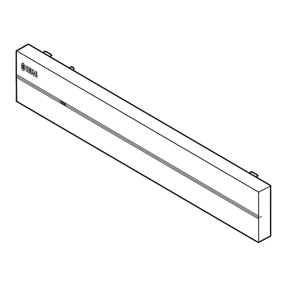
- Page 1 UAGLF Multi Zone Amplifier Amplificateur Multizone XDA-AMP5400RK OWNER’S MANUAL MODE D’EMPLOI MANUAL DE INSTRUCCIONES...
-
Page 2: Table Of Contents
CONTENTS BEFORE USING THE UNIT PLACEMENT AND CONNECTION Accessories ..............3 Placing the unit .............6 About this manual ............3 Mounting the unit on a rack ........ 6 Placing the unit without a rack ......6 Connecting devices .............7 PART NAMES AND FUNCTIONS Connecting speakers .......... -
Page 3: Before Using The Unit
• Due to product improvements, specifications and appearance optimum use. are subject to change without notice. • The illustrations in this manual are for instructional purposes only. • Access the Yamaha Downloads site to download the latest Owner’s Manual and Safety Brochure. http://download.yamaha.com/ En 3... -
Page 4: Part Names And Functions
PART NAMES AND FUNCTIONS Front panel a MAIN STATUS indicator c STATUS indicators Indicates the unit status depending on its color and whether it is Indicate the AMP1 - AMP4 status depending on whether they are lit or flashing. lit or flashing. –... -
Page 5: Rear Panel
Rear panel a GND screw terminal e TRIGGER IN 1– 4 jacks Connecting the source device chassis to the GND terminal of the Connection: 3.5 mm monaural mini-plug (Tip: + / Sleeve: -) unit may reduce noise in the signal. For inputting trigger signals (DC 12 V). -
Page 6: Placement And Connection
PLACEMENT AND CONNECTION Placing the unit Mounting the unit on a rack Use the supplied brackets to mount the unit on an EIA standard rack. Screw the brackets to the unit horizontally. Without the supplied front cover With the supplied front cover Placing the unit without a rack Notice •... -
Page 7: Connecting Devices
Connecting devices The following is an example of connecting the devices. Unplug the unit’s power cord from the AC wall outlet before connecting the devices. XDA-QS5400 Remote control device Remote control device Power amplifier (Infrared signal receiver) (Infrared signal transmitter) (i.e. -
Page 8: Connecting Speakers
• You must use the supplied Euroblock plugs. If the plugs have Use a commercially-available 3.5 mm monaural mini-plug cable. been lost, please contact your Yamaha dealer. For connecting to an infrared signal receiver/emitter that allows • Recommended cable gauges for the Euroblock plug: AWG26 you to operate the unit and other devices from another room. -
Page 9: Connection Examples
Connection examples Example 1 Source1 Speaker1 AMP1 Source2 Speaker2 AMP2 Source3 Speaker3 AMP3 Source4 Speaker4 AMP4 Speaker1 Source1 Speaker 3 Source3 Speaker2 Source2 Speaker 4 Source4 Example 2 Source1 Speaker1 AMP1 Speaker2 AMP2 Source2 Speaker3 AMP3 Speaker4 AMP4 Speaker1 Speaker2 Source1 Jumper plug x 4 Speaker3... - Page 10 Example 3 Source1 Speaker1 AMP1 Source2 Speaker2 AMP2 Speaker3 AMP3 Speaker4 AMP4 Speaker1 Source1 Jumper plug x 4 Source2 Speaker2 Speaker3 Speaker4 Example 4 Stereo Source1 Speaker1 AMP1 Speaker2 AMP2 Speaker3 AMP3 Speaker4 AMP4 Jumper plug x 6 Source1 Speaker1 Speaker2 Speaker3 Speaker4...
- Page 11 Example 5 Mono Speaker1 Source1 AMP1 Speaker2 AMP2 Speaker3 AMP3 Speaker4 AMP4 Jumper plug x 6 Monaural RCA cable x 1 Source1 Mono Mono Mono Mono Mono Mono Mono Mono Mono Speaker1 Speaker2 Speaker3 Speaker4 Example 6 Source1 Speaker1 AMP1 Source2 Speaker2 AMP2...
- Page 12 Example 7 Source1 AMP1 Speaker1 AMP2 AMP3 Speaker2 AMP4 Monaural RCA cable x 2 Source1 Speaker1 Speaker2 (High Power) (High Power) 12 En...
-
Page 13: Specifications
SPECIFICATIONS Specifications The specifications of the unit are as follows. Maximum Effective Output Power (JEITA) • (1-channel driven, 1 kHz, 10% THD, NORMAL, 4/8 Ω) Input jacks 130/65 W • (1-channel driven, 1 kHz, 10% THD, BRIDGE 8 Ω) 260 W Analog Audio •... - Page 14 * The contents of this manual apply to the latest specifications 437 x 46 x 453 mm (17-1/4" x 1-3/4" x 17-7/8") as of the publishing date. To obtain the latest manual, access the Yamaha website then download the manual file. 17-1/4" 14 En...
- Page 15 En 15...
- Page 16 TABLE DES MATIÈRES AVANT D’UTILISER L’UNITÉ POSITIONNEMENT ET CONNEXION Accessoires ..............17 À propos de ce mode d’emploi ......17 Positionnement de l’unité ........20 Montage de l’unité sur un rack ......20 NOMS DE PIÈCES ET FONCTIONS 18 Positionnement de l’unité sans rack ....20 Raccordement des appareils .........
-
Page 17: Avant D'utiliser L'unité
être modifiées sans avis préalable. • Les illustrations figurant dans ce manuel servent uniquement à expliciter les instructions. • Accédez au site de téléchargement Yamaha pour télécharger le mode d’emploi et la brochure sur la sécurité les plus récents. -
Page 18: Noms De Pièces Et Fonctions
NOMS DE PIÈCES ET FONCTIONS Face avant a Témoin MAIN STATUS c Témoins STATUS Indique le statut de l’unité en fonction de sa couleur et de son Indique le statut AMP1 - AMP4 selon qu’ils sont allumés ou état allumé ou clignotant. clignotent. -
Page 19: Face Arrière
Face arrière a Borne à vis GND e Prises TRIGGER IN 1–4 Le raccordement du châssis de l’appareil source à la borne GND Connexion : mini-fiche mono de 3,5 mm (pointe : + / manchon : -) de l’unité permet de réduire le bruit du signal. Pour recevoir des signaux de déclenchement (CC 12 V) Chaque AMP est mis sous tension à... -
Page 20: Positionnement Et Connexion
POSITIONNEMENT ET CONNEXION Positionnement de l’unité Montage de l’unité sur un rack Utilisez les supports fournis pour monter l’unité sur un rack à la norme EIA. Vissez les supports à l’unité horizontalement. Sans le couvercle avant fourni Avec le couvercle avant fourni Positionnement de l’unité... -
Page 21: Raccordement Des Appareils
Raccordement des appareils Voici un exemple de raccordement des appareils. Débranchez le cordon d’alimentation de l’unité de la prise secteur avant de raccorder les appareils. XDA-QS5400 Télécommande (récepteur Télécommande (émetteur Amplificateur de puissance de signaux infrarouges) de signaux infrarouges) (À savoir le XDA-AMP5400) L’unité... -
Page 22: Raccordement Des Enceintes
• Vous devez utiliser le bornier Euroblock fourni. Si vous avez Pour plus d’informations sur les configurations avec les perdu le bornier, veuillez contacter votre revendeur Yamaha. connecteurs cavaliers fournis et les câbles RCA mono, reportez- • Types de câble recommandés pour le bornier Euroblock : vous à... -
Page 23: Exemples De Connexion
Exemples de connexion Exemple 1 Source 1 Enceinte 1 AMP1 Source 2 Enceinte 2 AMP2 Source 3 Enceinte 3 AMP3 Source 4 Enceinte 4 AMP4 Enceinte 1 Source 1 Enceinte 3 Source 3 Enceinte 2 Source 2 Enceinte 4 Source 4 Exemple 2 Source 1 Enceinte 1... - Page 24 Exemple 3 Source 1 Enceinte 1 AMP1 Source 2 Enceinte 2 AMP2 Enceinte 3 AMP3 Enceinte 4 AMP4 Enceinte 1 Source 1 Connecteur cavalier x 4 Source 2 Enceinte 2 Enceinte 3 Enceinte 4 Exemple 4 Stereo Source 1 Enceinte 1 AMP1 Enceinte 2 AMP2...
- Page 25 Exemple 5 Mono Source 1 Enceinte 1 AMP1 Enceinte 2 AMP2 Enceinte 3 AMP3 Enceinte 4 AMP4 Connecteur cavalier x 6 Câble RCA mono x 1 Mono Source 1 Mono Mono Mono Mono Mono Mono Mono Mono Enceinte 1 Enceinte 4 Enceinte 2 Enceinte 3 Exemple 6...
- Page 26 Exemple 7 Source 1 AMP1 Enceinte 1 AMP2 AMP3 Enceinte 2 AMP4 Câble RCA mono x 2 Source 2 Enceinte 1 Enceinte 2 (Puissance élevée) (Puissance élevée) 26 Fr...
-
Page 27: Caractéristiques Techniques
CARACTÉRISTIQUES TECHNIQUES Caractéristiques techniques Les caractéristiques techniques de l’unité sont les suivantes. Puissance de sortie effective maximale (JEITA) • (une voie, 1 kHz, 10% DHT, NORMAL, 4/8 Ω) 130/65 W • (une voie, 1 kHz, 10 % DHT, BRIDGE, 8 Ω) Prises d’entrée 260 W Audio analogique... - Page 28 437 x 46 x 453 mm caractéristiques techniques connues à la date de publication du manuel. Pour obtenir la version la plus récente du manuel, accédez au site Web de Yamaha puis téléchargez le fichier du manuel concerné. 17-1/4" 28 Fr...
- Page 29 Fr 29...
- Page 30 CONTENIDO ANTES DE UTILIZAR LA UNIDAD 31 COLOCACIÓN Y CONEXIÓN Accesorios ..............31 Colocación de la unidad ......... 34 Acerca de este manual ..........31 Montaje de la unidad en un bastidor .... 34 Colocación de la unidad sin un bastidor ..34 Conexión de los dispositivos .........
-
Page 31: Antes De Utilizar La Unidad
• Debido a mejoras del producto, las especificaciones y la apariencia están sujetas a cambios sin previo aviso. • Las figuras de este manual solo tienen propósitos ilustrativos. • Visite el sitio de Descargas de Yamaha para descargar los Manuales de instrucciones y los Folletos de seguridad más recientes. -
Page 32: Nombres Y Funciones De Las Piezas
NOMBRES Y FUNCIONES DE LAS PIEZAS Panel delantero a Indicador MAIN STATUS c Indicadores STATUS Indica el estado de la unidad en función de su color y de si está Indican el estado de AMP1 - AMP4 en función de si están encendido o parpadeando. -
Page 33: Panel Trasero
Panel trasero a Terminal de tornillos GND e Tomas TRIGGER IN 1–4 Si conecta el chasis del dispositivo fuente al terminal GND de la Conexión: Miniconector monoaural de 3,5 mm (punta: +/ unidad, puede reducirse el ruido de la señal. manguito: -) Para recibir señales de activación (12 V CC). -
Page 34: Colocación Y Conexión
COLOCACIÓN Y CONEXIÓN Colocación de la unidad Montaje de la unidad en un bastidor Utilice los soportes suministrados para montar la unidad en un bastidor que cumple con el estándar EIA. Atornille los soportes a la unidad de forma horizontal. Sin la cubierta frontal suministrada Con la cubierta frontal suministrada Aviso... -
Page 35: Conexión De Los Dispositivos
Conexión de los dispositivos A continuación se indica un ejemplo de cómo conectar los dispositivos. Desenchufe el cable de alimentación de la unidad de la toma de CA antes de conectar los dispositivos. XDA-QS5400 Mando a distancia Mando a distancia Amplificador de potencia (receptor de señales (transmisor de señales... -
Page 36: Conexión De Los Altavoces
RCA monoaurales y los enchufes de conexión puente ha extraviado, póngase en contacto con su distribuidor de suministrados, consulte lo siguiente: Yamaha. • “Ejemplos de conexiones” (p.37) • Calibres de cable recomendados para el conector Euroblock: Para un mando a distancia... -
Page 37: Ejemplos De Conexiones
Ejemplos de conexiones Ejemplo 1 Entrada1 Altavoz1 AMP1 Entrada2 Altavoz2 AMP2 Entrada3 Altavoz3 AMP3 Entrada4 Altavoz4 AMP4 Altavoz1 Entrada1 Altavoz3 Entrada3 Altavoz2 Entrada2 Altavoz4 Entrada4 Ejemplo 2 Entrada1 Altavoz1 AMP1 Altavoz2 AMP2 Entrada2 Altavoz3 AMP3 Altavoz4 AMP4 Altavoz1 Altavoz2 Entrada1 Enchufe de conexión puente ×... - Page 38 Ejemplo 3 Entrada1 Altavoz1 AMP1 Entrada2 Altavoz2 AMP2 Altavoz3 AMP3 Altavoz4 AMP4 Altavoz1 Entrada1 Enchufe de conexión puente × 4 Entrada2 Altavoz2 Altavoz4 Altavoz3 Ejemplo 4 Estéreo Entrada1 Altavoz1 AMP1 Altavoz2 AMP2 Altavoz3 AMP3 Altavoz4 AMP4 Enchufe de conexión puente × 6 Entrada1 Altavoz1 Altavoz2...
- Page 39 Ejemplo 5 Mono Entrada1 Altavoz1 AMP1 Altavoz2 AMP2 Altavoz3 AMP3 Altavoz4 AMP4 Enchufe de conexión puente × 6 Cable RCA monoaural × 1 Mono Entrada1 Mono Mono Mono Mono Mono Mono Mono Mono Altavoz4 Altavoz1 Altavoz2 Altavoz3 Ejemplo 6 Entrada1 Altavoz1 AMP1 Entrada2...
- Page 40 Ejemplo 7 Entrada1 AMP1 Altavoz1 AMP2 AMP3 Altavoz2 AMP4 Cable RCA monoaural × 2 Entrada1 Altavoz2 Altavoz1 (Alta potencia) (Alta potencia) 40 Es...
-
Page 41: Especificaciones
ESPECIFICACIONES Especificaciones A continuación se indican las especificaciones de la unidad. Potencia de salida efectiva máxima (JEITA) • (Dirigida por 1 canales, 1 kHz, 10% THD, NORMAL, 4/8 Ω) Tomas de entrada 130/65 W • (Dirigida por 1 canal, 1 kHz, 10 % THD, BRIDGE, Audio analógico 8 Ω) 260 W... - Page 42 * El contenido de este manual se aplica a las especificaciones 437 × 46 × 453 mm más recientes en la fecha de publicación. Para obtener el manual más reciente, visite el sitio web de Yamaha y descargue el archivo del manual. 17-1/4"...
- Page 43 Es 43...
- Page 44 Yamaha Global Site https://www.yamaha.com/ Yamaha Downloads https://download.yamaha.com/ Manual Development Group © 2018 Yamaha Corporation Published 12/2018 NVEM-B0 VCM9320...
Need help?
Do you have a question about the XDA-AMP5400RK and is the answer not in the manual?
Questions and answers