Table of Contents
Advertisement
Advertisement
Table of Contents

Summary of Contents for Yamaha XM6150
- Page 1 POWER AMPLIFIER XM6150 XM4220 Owner’s Manual...
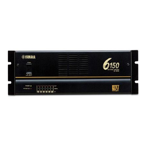
- Page 2 • Variable-speed, low-noise cooling fan system ensures high reliability even under the most demanding conditions. This Owner’s Manual applies to the XM6150 6CH and XM4220 4CH power amplifier. In order to take full advantage of your power amplifier and enjoy long and trouble-free operation, please read this Owner’s Manual carefully before using your XM Series Power Amplifier.
-
Page 3: Table Of Contents
Precautions Warnings • Do not allow water to enter this unit or allow the unit to become wet. Fire or electrical shock may result. • Connect this unit’s power cord only to an AC outlet of the type stated in this Owner’s Manual or as marked on the unit. Failure to do so is a fire and electrical shock hazard. -
Page 4: Controls And Functions
See the Precautions section of this Owner’s Manual for ways to prevent the amplifier overheating. * The illustration shows model XM6150. CLIP indicator A channel’s CLIP indicator lights up when its output distortion exceeds 1% (i.e., clipping). Output signal clipping is typically caused by excessive input signal levels. -
Page 5: Rear Panel
BRIDGE switches These switches are used to bridge the following channel pairs: A–B, C–D, and E–F (XM6150 only). When set to OFF, the two channels operate indepen- dently. For example, the signal connected to input channel A is amplified and output by the channel A outputs, while the signal connected to input channel B is amplified and output by the channel B outputs. - Page 6 For each channel, you can connect speakers as long as the speakers’ total rated input does not exceed 150W (for XM6150) or 350W (for XM4220). Note: Be sure to use speakers that support the 70V –...
-
Page 7: Connection
Connection Using a Euroblock connector 1. If the wire insertion ports are closed, turn the screws on top of the connector counterclockwise to open the ports. 2. Insert the wires into the appropriate ports, following the indication of the pole on the input terminal, turn the screws on top of the connector clockwise to fix the wires. -
Page 8: Air Flow
The figure on the left below shows an example of a fan kit (panels and two fans) on the top slot of the rack. The fans are Minebia 3115PS-12T-B30 (with 0.9 m The figure on the right below is a dimensional diagram of a panel on which two 3115PS-12T-B30 are installed. Fan kit XM6150/4220 Ventilation panel XM6150/4220 Air exhaust O or more maximum static pressure. -
Page 9: Specifications
Specifications subject to change without notice. For European Model Purchaser/User information specified in EN55103-1 and EN55103-2. Inrush Current: 56A Conformed Enviroment: E1, E2, E3 and E4. XM6150 100 W x 6 120 W x 6 8 /BRIDGE 240 W x 3... -
Page 10: Block Diagram
Block Diagram... -
Page 11: Dimensions
Dimensions W: 480 Unit: mm... -
Page 12: Troubleshooting
4 (8 in Bridge mode). Check the ventilation around the amplifier and improve the airflow if necessary. Consult your dealer or a Yamaha service center. Protection Circuit The PC limiter circuit activates to protect the power transistors. The thermal protection... - Page 13 YAMAHA CORPORATION V455890 R0 1 AP 16 Pro Audio Division, #18/3 P.O. Box 3, Hamamatsu, 430-8651, Japan NP Printed in Taiwan...


Need help?
Do you have a question about the XM6150 and is the answer not in the manual?
Questions and answers