
Related Manuals for Yamaha 150


Summary of Contents for Yamaha 150
-
Page 1: Power Amplifier
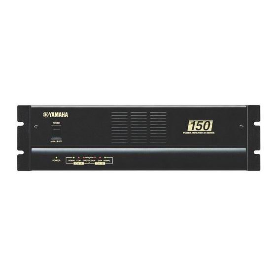
POWER AMPLIFIER XH150 Owner’s Manual POWER POWER AMPLIFIER XH SERIES POWER SIGNAL CLIP PROTECTION CLIP SIGNAL CH A CH B... - Page 2 • The unit is equipped with two types of inputs (balanced XLR and barrier strip) and one barrier strip output. • The voltage line is switchable between 100 V and 70 V, and output is rated at 150 W. The high-impedance design makes the unit most suitable for driving multiple speaker systems simultaneously in a facility.
-
Page 3: Table Of Contents
Precautions • Connect this unit’s power cord only to an AC outlet of the type stated in this Owner’s Manual or as marked on the unit. Failure to do so is a fire and electrical shock hazard. • Do not allow water to enter this unit or allow the unit to become wet. -
Page 4: Controls And Functions
Controls and Functions Front Panel POWER switch and indicator This is the main POWER switch. Press to power ON the amplifier. Press again to power OFF. The POWER indicator lights up when the amplifier is powered ON. SIGNAL indicators These green LED indicators light up when the respective channel’s output signal exceeds 4 Vrms. -
Page 5: Rear Panel
Rear Panel FILTER CHANNEL B CHANNEL A LOW CUT LOW CUT 40Hz 40Hz 80Hz 80Hz HIGH CUT HIGH CUT 5kHz 5kHz 10kHz 10kHz INPUT CHANNEL B CHANNEL A FILTER switches (CHANNEL A, B) Independent low-cut/high-cut filters are provided for channels A and B. These filters allow you to change cut-off frequencies. -
Page 6: Connecting Speakers
The number of speakers that can be connected varies depending on the speakers’ rated input. You can connect speakers with a total rated input per channel of up to 150 W. Total rated input of up to 150 W For example, if you are using speakers with a rated input of 15 W, you can connect up to ten speakers. - Page 7 You can also connect multiple speakers with a different rated input to a single channel. For example, you can connect ten speakers with a rated input of 5 W and ten speakers with a rated input of 10 W (total 150 W), as shown below:...
-
Page 8: Caution For Connection
Caution for Connection 1. Turn off the POWER switch. 2. Remove the cover attachment screws and remove the protective cover from the speaker terminals. 3. After removing approx. 15 mm of insulation from the ends of the speaker cables, bind the bare ends of the speaker wires in the corresponding speaker terminals and tighten the terminals to securely clamp the wires. -
Page 9: Rack Mounting
Rack Mounting Mounting in an EIA standard rack If multiple high-power amp units are mounted in a rack with poor ventilation, the heat from the amps will cause the interior of the amp to become very hot, causing the performance of the amps to be impaired. In particular, when mounting in a rack whose back can not be left open, mount according to the following instructions. -
Page 10: General Specifications
Specifications subject to change without notice. For European Model Purchaser/User Information specified in EN55103-1 and EN55103-2. Inrush Current: 20A Conformed Environment: E1, E2, E3 and E4 150 W + 150 W = 64 /100 V, R Half Power 10 Hz~40 kHz (THD+N= 0.1%) 0.1% +0.5, –1 dB... -
Page 11: Block Diagram
Block Diagram INPUT CHANNEL A 80Hz 40Hz – CHANNEL A LOW CUT INPUT – CHANNEL B INPUT CHANNEL B 80Hz 40Hz LOW CUT Dimensions CHANNEL A 10kHz 5kHz HIGH CUT 100V OUTPUT VOLTAGE CHANNEL B 10kHz 5kHz HIGH CUT W:480 SIGNAL CLIP PROTECTION... -
Page 12: Troubleshooting
100 V. Check the amplifier ventilation conditions and take appropriate measures to improve airflow around the amplifier. Consult your dealer or nearest Yamaha service center. Remedy Protection Circuit The PC limiter circuit operates to protect the power transistors. The thermal protection... - Page 13 YAMAHA CORPORATION V294640 R2 1 IP 16 Pro Audio Division, #18/3 P.O. Box 3, Hamamatsu, 430-8651, Japan NP Printed in Taiwan...
Need help?
Do you have a question about the 150 and is the answer not in the manual?
Questions and answers