Allen-Bradley 1747-SN Installation Instructions Manual
Remote i/o scanner
Hide thumbs
Also See for 1747-SN:
- Installation instructions manual (12 pages) ,
- User manual (188 pages)
Table of Contents
Advertisement
Quick Links
Download this manual
See also:
User Manual
Advertisement
Table of Contents

Related Manuals for Allen-Bradley 1747-SN


Summary of Contents for Allen-Bradley 1747-SN
- Page 1 Remote I/O Scanner Catalog Number 1747-SN Installation Instructions Publication 1747-5.33...
-
Page 2: Important User Information
Reproduction of the contents of this copyrighted publication, in whole or in part, without written permission of Allen-Bradley Company, Inc., is prohibited. Throughout this manual we use notes to make you aware of safety... -
Page 3: Related Publications
• Calling (440) 646-5436 for the Allen-Bradley Fax Back service. You will be faxed information on the topic you request. Ordering a manual using one of the following methods: •... - Page 4 SLC system so that the scanner only transfers the discrete I/O data required by your application program. The 1747-SN Series B or later RIO Scanner can be configured to transfer up to 64 words of data to a remote device via block transfer.
-
Page 5: Hardware Features
MOUNTING BOLT. REFER TO USERS MANUAL. Line 1 Shield Line 2 1747-SN Cable Tie Slots RIO Link Connector Dip Switch RIO Link Connector This 3-pin male connector connects the scanner to the RIO link. The Allen-Bradley repair part number is 1746-RT29. Publication 1747-5.33... -
Page 6: Status Leds
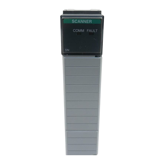
Remote I/O Scanner Status LEDs The scanner has two LEDs, FAULT and COMM, which indicate its operating status. FAULT LED - indicates the scanner’s overall status. The red FAULT LED is off whenever the scanner is configured and operating properly. COMM LED - allows you to monitor communication with all configured devices. -
Page 7: Required Tools And Equipment
Remote I/O Scanner Baud Rate DIP Switch The figure below shows the location of the DIP switch and the DIP switch settings for the supported baud rates. Important: For proper system operation, the baud rate of all devices on the RIO link must be the same. 57.6K baud 115.2K baud 230.4K baud... -
Page 8: Installation
Remote I/O Scanner Installation ATTENTION: Disconnect system power before attempting to install, remove, or wire the module. Make sure you have set the DIP switch properly before installing the scanner. Important: Before installation, make sure that your modular SLC power supply has adequate reserve current capacity. The scanner requires 600 mA at 5V dc. -
Page 9: Rio Link Wiring
Remote I/O Scanner 5. Insert the cable tie in the slots. 6. Route the cable down and away from module, securing it with the cable tie. 7. Cover all unused slots with the Card Slot Filler, Catalog Number 1746-N2. Removal 1. - Page 10 Remote I/O Scanner Terminating Resistor Last Physical Device End RIO Scanner RIO Link RIO Link Connector Terminating Connector Resistor Scanner End Line 1 – Blue Shield – Shield Line 2 – Clear Shield Drain Wire (For Series A Retrofits) Ring Lug Shield Chassis Mounting Drain Wire...
-
Page 11: Specifications
Remote I/O Scanner For Series A Scanner Retrofits Refer to the illustration on page 10. To eliminate the need to strip the cable back, follow these steps: 1. Attach the shield wire and a short piece of #20 AWG wire (dotted line) to the shield lug of the RIO link connector. - Page 12 PLC is a registered trademark of the Rockwell Automation, Inc. SLC, SLC 500, SLC 5/02, PanelView, RediPANEL, Dataliner, Flex I/O, PLC–5/15, PLC–5/12, PLC–5/25, PLC–5/30, PLC–5/40, PLC–5/60 are trademarks of Rockwell Automation, Inc. Belden is a trademark of Belden, Inc. Publication 1747-5.33 – August 1998 40071-039-01(A) ©...
Need help?
Do you have a question about the 1747-SN and is the answer not in the manual?
Questions and answers