Table of Contents
Advertisement
Instruction Manual
D103300X012
March 2010
r
Fisher
8580 Rotary Valve
Contents
. . . . . . . . . . . . . . . . . . . . . . . . . . . . . . . . .
. . . . . . . . . . . . . . . . . . . . . . . . .
. . . . . . . . . . . . . . . . . . . . . . . . . . . . . .
. . . . . . . . . . . . . . . . . . . . . . . . . . . .
. . . . . . . . . . . . . . . . . . . . . . . . . . . . . . . . . .
. . . . . . . . . . . . . . . . . . . . . . . . . . . . . . . .
. . . . . . . . . . . . . . . . . . . . . . . . . . . .
. . . . . . . . . . . . . . . . . . . . . . . . . . . . . . . .
. . . . . . . . . . . . . . . . . . . . . . . . . . . . . . . .
Introduction
Scope of Manual
This instruction manual includes installation,
maintenance, and parts information for the Fisher
8580 valve, DN50 through DN300 or NPS 2 through
NPS 12 (figure 1). Refer to separate instruction
manuals for information covering the power on-off
actuator and accessories.
Do not install, operate, or maintain an 8580 valve
without being fully trained and qualified in valve,
actuator, and accessory installation, operation, and
maintenance. To avoid personal injury or property
damage, it is important to carefully read, understand,
and follow all the contents of this manual, including
all safety cautions and warnings. If you have any
questions about these instructions, contact your
Emerson Process Management sales office before
proceeding.
www.Fisher.com
. . . . . . . . . . . . . . . . . . . . .
. . . . . . . . .
. . . . .
. . . . . . . . . . . . . . . . . . . . . . .
1
1
3
2
4
6
7
11
11
15
17
17
18
W9498
W9425
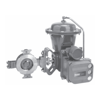
Figure 1. Fisher 8580 Valve with 2052 Actuator
and DVC6000 Digital Valve Controller
8580 Valve
SINGLE FLANGE STYLE
WAFER STYLE
Advertisement
Table of Contents

Related Manuals for Emerson Fisher 8580


Summary of Contents for Emerson Fisher 8580
-
Page 1: Table Of Contents
If you have any questions about these instructions, contact your Figure 1. Fisher 8580 Valve with 2052 Actuator Emerson Process Management sales office before and DVC6000 Digital Valve Controller proceeding. -
Page 2: Specifications
Instruction Manual 8580 Valve March 2010 Table 1. Fisher 8580 Valve Specifications Specifications ASME Valve Body Size DN 50, 80, 100, 150, 200, 250, and 300 NPS 2, 3, 4, 6, 8, 10, and 12 Pressure Rating PN 10 to 40 per EN 12516-1 CL150 and 300 per ASME B16.34... -
Page 3: Description
1. Minimum allowable temperature for PN series flanges is 10_C (14_F). See requirements of EN 13445-2 Annex B for applications below 10_C (14_F) with PN series flanges. 2. For applications exceeding 316_C (600_F), consult your Emerson Process Management sales office for appropriate disk material selection. -
Page 4: Installation
Emerson schedule 80 pipe or compatible EN Process Management sales office. pipe sizes. If piping with a smaller... - Page 5 Instruction Manual 8580 Valve March 2010 Table 5. Stud Bolt Data WAFER STYLE VALVE SIZE PN 10 PN 16 PN 25 PN 40 Size Dia Size Dia Size Dia Size Dia No. of No. of No. of No. of & Dimen- &...
-
Page 6: Maintenance
Instruction Manual 8580 Valve March 2010 to a discharge of static electricity from CAUTION the valve components. To avoid personal injury or property damage, always make sure the valve body is 8580 disk rotation is counterclockwise grounded to the pipeline before to open (when viewed from the putting the control valve assembly into actuator side of the valve body, see... -
Page 7: Packing Maintenance
Instruction Manual 8580 Valve March 2010 D Vent the power actuator loading pressure and relieve any spring precompression. D Use lock-out procedures to be sure the above measures stay in effect while you work on the equipment. D The valve packing box may contain process fluids that are pressurized, even when the valve has been removed from the pipeline. - Page 8 Instruction Manual 8580 Valve March 2010 GE39986-A PTFE V‐RING GRAPHITE RIBBON GE39901-A STANDARD PACKING GE40113-A SINGLE PTFE PACKING GRAPHITE PACKING GE40118-A ENVIRO‐SEAL PACKING NOTES: THESE TWO SURFACES SHOULD REMAIN PARALLEL AS YOU WITH CONDUCTIVE PACKING, THE FEMALE ADAPTOR IN PTFE ALTERNATELY AND EVENLY TIGHTEN THE PACKING NUTS (KEY 28).
- Page 9 Instruction Manual 8580 Valve March 2010 If the packing is relatively new and tight on the shaft, injury, stay clear of the disk edges and if tightening the packing flange nuts does not when rotating the disk (key 3). stop leakage, the shaft may be worn or nicked so that a seal cannot be made.
- Page 10 Instruction Manual 8580 Valve March 2010 For valves with ENVIRO-SEAL packing systems: WARNING 1. Isolate the control valve from the line pressure, release pressure from both sides of the valve body, and drain the process media from both sides of the Do not lubricate parts when used in valve.
-
Page 11: Replacing The Seal Ring Assembly
Instruction Manual 8580 Valve March 2010 page 15 of this manual, before returning the valve to 2. Unscrew the flange bolts, and remove the valve service. from the pipeline. 3. Unscrew the machine screws (key 14), remove the retainer clip (key 13), and remove the seal Replacing the Seal Ring Assembly retainer (key 2). - Page 12 Instruction Manual 8580 Valve March 2010 BACKSIDE OF VALVE BEARING TAB BEARING TAB Figure 5. Orientation of Bearing Tabs Table 6. Follower Shaft Internal Threads CAUTION VALVE SIZE THREAD SIZE M8 X 1.25 When removing the actuator in the M10 X 1.50 following step, use a wheel puller to M12 X 1.75 separate the actuator parts from the...
- Page 13 Instruction Manual 8580 Valve March 2010 Assembly Table 7. Recommended Blind Flange Bolt Torque VALVE SIZE TORQUE lbfSft WARNING 50 to 150 2 to 6 200, 250 8, 10 Do not lubricate bearings that will be used for oxygen service, or where the lubrication is incompatible with the process media.
- Page 14 Instruction Manual 8580 Valve March 2010 “T” STAMPED ON ACTUATOR END OF DISK TAPER/EXPANSION PIN LOCATION W9486 INSTALL THE PINS FROM THIS SIDE OF THE DISK. Figure 6. Taper / Expansion Pin Installation 7. Attach the seal retainer (key 2) and the retainer Table 8.
-
Page 15: Actuator Mounting
Instruction Manual 8580 Valve March 2010 Actuator Mounting With the valve body out of the line, mount the actuator on the valve body in accordance with the instructions in the actuator instruction manual. Mount the actuator yoke to the valve body, and tighten the actuator-mounting cap screws and nuts (keys 35 and 36) to the appropriate torque from table 8. - Page 16 Instruction Manual 8580 Valve March 2010 ACTUATOR ROD ACTUATOR ROD END BEARING ACTUATOR LEVER LEVER INDEX MARKS (4) VALVE SHAFT INDEX MARK TYPICAL ACTUATOR (TYPE 1052) SECTIONAL THROUGH HOUSING A3344/IL MOUNTING MOUNTING MOUNTING MOUNTING ACTUATOR VALVE CLOSED POSITION 1 POSITION 2 POSITION 3 POSITION 4 MOUNTING...
-
Page 17: Parts Ordering
Worn shafts, packing box damage, or other components that do not meet Emerson Process Note Management finish specifications, dimensional Neither Emerson, Emerson Process tolerances, and design specifications, may adversely Management, nor any of their affiliated alter the performance of the retrofit kit. -
Page 18: Parts List
Expansion Pin (continued) S20910 Note DN 50 (NPS 2) GE27079X012 DN 80 (NPS 3) GE21165X012 For part numbers not shown, contact your Emerson DN 100 (NPS 4) GE23792X012 Process Management sales office. DN 150 (NPS 6) GE16687X012 Description Part Number... - Page 19 Instruction Manual 8580 Valve March 2010 Figure 10. Fisher 8580 Valve Assembly GE36048_D Description Part Number Description Part Number Packing Ring (4 req’d) Packing Set, ENVIRO-SEAL Graphite ribbon Graphite DN 50 (NPS 2) 12A9134X012 DN 50 (NPS 2) 13B8816X012 DN 80 (NPS 3)
- Page 20 *Recommended spare parts Fisher and ENVIRO-SEAL are marks owned by one of the companies in the Emerson Process Management business division of Emerson Electric Co. Emerson Process Management, Emerson, and the Emerson logo are trademarks and service marks of Emerson Electric Co. All other marks are the property of their respective owners.
Need help?
Do you have a question about the Fisher 8580 and is the answer not in the manual?
Questions and answers