Advertisement
Instruction Manual
D103815X012
May 2020
850 and 950 Series Pressure/Vacuum Relief
Valve (ATEX Approved)
P1854
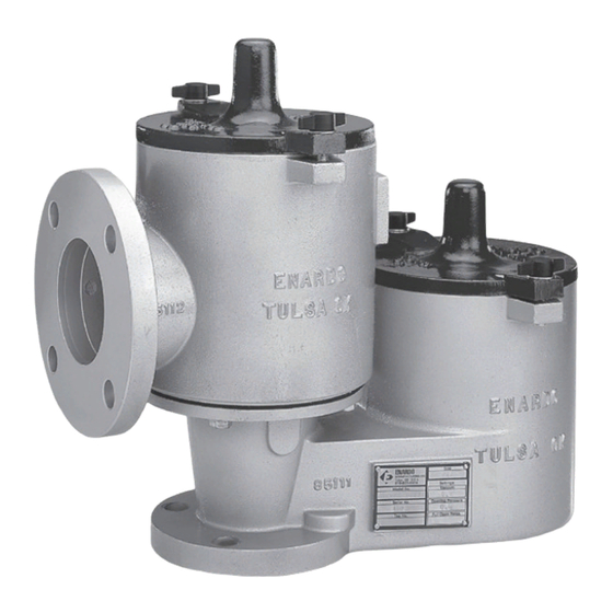
MODEL 850
P1854
Figure 1. 850 and 950 Series Pressure/Vacuum Relief Valve
Table of Contents
Introduction .................................................................. 3
Specifications .............................................................. 2
Product Identification and Marking .............................. 4
Principle of Operation .................................................. 5
Installation ................................................................... 8
Maintenance .............................................................. 11
Adjustments ............................................................... 14
Valve Repair .............................................................. 15
MODEL 950
850 and 950 Series
MODEL 850
Figure 2. 850 and 950 Series with Smart Wireless option
WARNING
!
Failure to follow these instructions or
to properly install and maintain this
equipment could result in an explosion,
fire and/or chemical contamination
causing property damage and personal
injury or death.
Enardo™ pressure/vacuum relief valve
must be installed, operated and maintained
in accordance with federal, state and
local codes, rules and regulations,
and Emerson Process Management
Regulator Technologies Tulsa, LLC
(Emerson) instructions.
MODEL 950
Advertisement


Need help?
Do you have a question about the Enardo 850 Series and is the answer not in the manual?
Questions and answers