Table of Contents
Advertisement
Quick Links
Instruction Manual
D104709X012
Fisher
8540 Eccentric Disk
™
Butterfly Control Valve
Contents
. . . . . . . . . . . . . . . . . . . . . . . . . . . . . . . . .
. . . . . . . . . . . . . . . . . . . . . . . . . . . . .
. . . . . . . . . . . . . . . . . . . . . . . . . . . . . . . . .
. . . . . . . . . . . . . . . . . . . . . . . . . . . . . . .
. . . . . . . . . . . . . . . . . . . . . . . . . . . . . . . . . .
. . . . . . . . . . . . . . . . . . . . . . . . . . . .
. . . . . . . . . . . . . . . . . . . . . . . . . . . . . . . . .
. . . . . . . . . . . . . . . . . . . . . . . . .
. . . . . . . . . . . . . . . . . . . . . . . . . . . . . . .
. . . . . . . . . . . . . . . . . . . . . . . . . . . . . . . . . . .
Introduction
Scope of Manual
This instruction manual includes installation, maintenance, and parts information for the 8540 Eccentric Disk Butterfly
Control Valve (see figure 1). Refer to separate instruction manuals for information covering the actuator and
accessories.
Do not install, operate, or maintain 8540 valves without being fully trained and qualified in valve,
actuator, and accessory installation, operation, and maintenance. To avoid personal injury or property
damage, it is important to carefully read, understand, and follow all the contents of this manual,
including all safety cautions and warnings. If you have any questions about these instructions, contact
your
Emerson sales office
Description
The seal design of the 8540 eccentric disk high performance butterfly valve provides excellent shutoff capability. This
valve has a square drive shaft end and soft seal rings for use in a wide variety of applications.
www.Fisher.com
. . . . . . . . . . . . . . . . . . . . . . . . .
. . . . . . . . . . . . . . . . . . . . . .
. . . . . .
before proceeding.
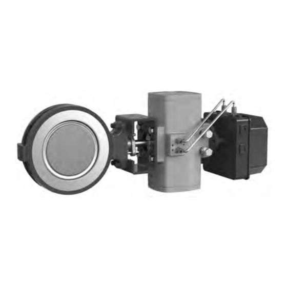
Figure 1. Fisher 8540 Butterfly Valve with Bettis RPE
Actuator and 3720 Positioner
1
1
1
2
2
4
8
9
11
15
18
19
X1846
20
8540 Valve
September 2021
Advertisement
Table of Contents

Related Manuals for Emerson Fisher 8540


Summary of Contents for Emerson Fisher 8540
-
Page 1: Table Of Contents
™ Butterfly Control Valve Contents Figure 1. Fisher 8540 Butterfly Valve with Bettis RPE Actuator and 3720 Positioner Introduction ....... . . -
Page 2: Specifications
Instruction Manual 8540 Valve September 2021 D104709X012 Table 1. Specifications Valve Size and End Connection Styles Flow Direction NPS J 3, J 4, J 6, J 8, J 10, and See figure 3 J 12 wafer body valves Actuator/Valve Action Maximum Inlet Pressure With the diaphragm or piston actuators, the valve Carbon Steel and Stainless Steel Valve Bodies:... - Page 3 To avoid possible personal injury and because some valve/trim material combinations are limited in their pressure drop and temperature ranges, do not apply any other conditions to the valve without first contacting your Emerson sales office. Table 3. Construction Material Temperature Limits...
-
Page 4: Valve Orientation
Instruction Manual 8540 Valve September 2021 D104709X012 Table 4. Maximum Allowable Pressure Drops at Temperature TEMPERATURE PRESSURE DROP Valve Orientation When installing the valve, it is recommended that the valve drive shaft be horizontal as shown in figure 1. Valve Direction The high performance butterfly valve is designed to allow flow in either direction when in the open position. - Page 5 Instruction Manual 8540 Valve D104709X012 September 2021 Figure 3. Flow Direction REVERSE FLOW RETAINER RING FORWARD FLOW FACE SIDE OF DISK Table 5. Stud Bolt Data WAFER STYLE CL150 CL300 VALVE SIZE, NPS Size Dia Size Dia No. of Stud Bolts A Dimension, Inch No.
- Page 6 Instruction Manual 8540 Valve September 2021 D104709X012 Installing the Valve in the Pipeline WARNING The edges of a rotating disk have a shearing effect that may result in personal injury. To help prevent such injury, stay clear of the disk edges when rotating the disk (key 3, figure 12). CAUTION Damage to the disk will occur if any pipe flanges or piping connected to the valve interfere with the disk rotation path.
- Page 7 Instruction Manual 8540 Valve D104709X012 September 2021 D Select and install two pipe line gaskets. 4. Install the remaining line flange bolting to secure the valve in the pipeline. Tighten the nuts to the line flange studs in a crisscross pattern to ensure proper alignment of valve, gaskets, and flanges. Packing Adjustment and Shaft Bonding WARNING Personal injury could result from packing leakage.
-
Page 8: Maintenance
Instruction Manual 8540 Valve September 2021 D104709X012 Figure 5. Optional Shaft-to-Valve Body Bonding Strap Assembly ACTUATOR MOUNTING BRACKET VALVE BODY VIEW A-A GH14001 Maintenance Valve parts are subject to normal wear and must be inspected and replaced as necessary. The frequency of inspection and replacement depends upon the severity of service conditions. -
Page 9: Packing Maintenance
Instruction Manual 8540 Valve D104709X012 September 2021 CAUTION During any of the following steps, do not rotate the disk past 90 degrees in the open direction. Rotating the disk past 90 degrees can damage the seal ring. Packing Maintenance PTFE‐filled packing has a partially conductive packing ring (such as a carbon‐filled PTFE female adaptor) to electrically bond the shaft to the valve body. - Page 10 Instruction Manual 8540 Valve September 2021 D104709X012 Figure 6. Typical Packing Arrangement PACKING FOLLOWER PACKING SET PACKING BOX RING PTFE V-RING PACKING C0785*A...
-
Page 11: Seal Ring Maintenance
Instruction Manual 8540 Valve D104709X012 September 2021 1. Install the new packing parts (see figure 6). Install the packing follower and finger tighten the packing flange nuts onto the studs only enough to stop leakage. 2. If the valve was equipped with a bonding strap assembly (figure 5), re‐install the assembly. 3. - Page 12 Instruction Manual 8540 Valve September 2021 D104709X012 Key numbers are shown in figure 12 unless otherwise noted. Disassembly Most maintenance procedures will require the actuator to be removed. 1. Isolate the control valve from line pressure, and relieve pressure from the valve body. Shut off and disconnect all lines from the power actuator.
- Page 13 Instruction Manual 8540 Valve D104709X012 September 2021 Figure 8. Disk Rotation Indication DISK STOP ACTUATOR TO OPEN END OF SHAFT DISK POSITION INDICATOR RETAINER RING DISK IN THE DISK IN THE CLOSED POSITION OPEN POSITION NOTE: SET ACTUATOR TRAVEL STOPS TO OBTAIN AN EQUAL DISTANCE TO DISK SURFACE AS SHOWN.
- Page 14 Instruction Manual 8540 Valve September 2021 D104709X012 c. Install the seal ring assembly into the slot in the valve body as shown in figure 9. Refer to Installing the retainer ring steps below. Figure 9. Available Seal Configurations VALVE RETAINING BODY RING SPRING...
-
Page 15: Disk, Drive Shaft And Bearing Maintenance
Instruction Manual 8540 Valve D104709X012 September 2021 3. Turn the disk into and out of the seal ring several times, to help break in the seal and reduce actuator torque requirements during adjustment. 4. If replacing the packing, remove all packing parts from the valve body. Upon re‐assembly of the valve, refer to the Packing Maintenance procedures to replace the packing. - Page 16 Instruction Manual 8540 Valve September 2021 D104709X012 When installing the bearings in the opposite side of the valve body bore, repeat the following procedures. D Position the bearing edge to match the valve body bore, and insert the one piece bearing/disk spacer into the bearing bore with the bearing tab facing away from the disk stop as shown in figure 10.
- Page 17 Instruction Manual 8540 Valve D104709X012 September 2021 10. Install the packing parts using the appropriate instructions provided in the Packing Maintenance procedures. Refer to the Actuator Mounting procedures before installing the valve in the pipeline. Table 6. Removal Tool Dimensions SHAFT DIAMETER 12.7 3.91...
-
Page 18: Actuator Mounting
Instruction Manual 8540 Valve September 2021 D104709X012 Figure 11. Taper Pin and Hallow Pin Removal and Installation 0.03 x 455 0.06 x 455 INSTALLATION TOOL 0.01 x 455 0.010 UNDERCUT PER SIDE REMOVAL TOOL DISK HUB INSTALLATION REMOVAL TOOL TOOL VALVE DISK HOLLOW PIN NOTE:... -
Page 19: Parts Ordering
WARNING Use only genuine Fisher replacement parts. Components that are not supplied by Emerson should not, under any circumstances, be used in any Fisher valve, because they may void your warranty, might adversely affect the performance... -
Page 20: Parts List
Drive Screw, w/ nameplate 21 Nameplate Note 22 Lead Seal & Wire (not shown) For part ordering information contact your Emerson sales office. 23 Bottom Cap, 12‐inch only 24 Bottom Cap Stud, 12‐inch only 25 Bottom Cap Hex Nut, 12‐inch only 27... - Page 21 Instruction Manual 8540 Valve D104709X012 September 2021 Figure 12. Fisher 8540 Valve Assembly PTFE PACKING 34B5064 TWO-PIECE FOLLOWER VIEW B PTFE SEAL NPS 12 VIEW B CL300 NOTE: KEYS 21, 22, 28, AND 115 ARE NOT SHOWN. GH13521...
- Page 22 Instruction Manual 8540 Valve September 2021 D104709X012...
- Page 23 Instruction Manual 8540 Valve D104709X012 September 2021...
- Page 24 Fisher is a mark owned by one of the companies in the Emerson Automation Solutions business division of Emerson Electric Co. Emerson Automation Solutions, Emerson, and the Emerson logo are trademarks and service marks of Emerson Electric Co. All other marks are the property of their respective owners.
Need help?
Do you have a question about the Fisher 8540 and is the answer not in the manual?
Questions and answers