
Related Manuals for AEROTECNICA COLTRI MCH-36


Summary of Contents for AEROTECNICA COLTRI MCH-36
- Page 1 w w w. c o l t r i s u b. c o m USE AND MAINTENANCE MANUAL Hight pressure compressor for breathing air and technical gases...
- Page 3 MCH-36 HIGH PRESSURE COMPRESSOR FOR BREATHING AIR AND TECHNICAL GASES IMPORTANT: BEFORE USING THE COMPRESSOR READ THIS MANUAL CAREFULLY Via Colli Storici, 177 25010 SAN MARTINO DELLA BATTAGLIA (BS)ITALY Tel. +39 030 9910301 Fax. +39 030 9910283 www.coltrisub.it www.coltrisub.com coltrisub@coltrisub.it...
- Page 4 Should you require any clarification, when using the compressor for the first time or at any other time it is used, please remember that AEROTECNICA COLTRI Srl is at your complete disposal.
- Page 5 EN 50082-2 (March 1995) DESENZANO DEL GARDA, date Chairman of the Board of Directors Carlo Coltri This manual is the property of AEROTECNICA COLTRI S.r.l. Reproduction, whole or partial, is forbidden M C H - 3 6 Use and maintenance manual pag.
-
Page 6: Table Of Contents
Contents CONTENTS CHAPTER 1 - GENERAL 1.1 Preliminary information 1.2 Required operator training 1.3 Important information for the user 1.4 Foreword 1.5 Warranty 1.6 Assistance 1.7 Responsibility 1.8 Purpose of the machine 1.9 Where the machine may be used 1.10 Running in and testing the compressor CHAPTER 2 - BASIC INFORMATION ON THE COMPRESSOR 2.1 Description of the compressor 2.2 Identifying the compressor... - Page 7 Contents CONTENTS CHAPTER 5 - HANDLING AND INSTALLATION 5.1 Unpacking 5.2 Handling 5.3 Installation 5.3.1 Positioning 5.3.2 Air intake extension connection 5.3.3 Reload hose connection 5.3.4 Electrical connection CHAPTER 6 - USING THE COMPRESSOR 6.1 Preliminary checks before using for the first time 6.1.1 Filling with lubricant oil 6.1.2 Checking for proper electrical connection 6.2 Checks to be run at the start of each working day...
- Page 8 Contents CONTENTS CHAPTER 7 - MAINTENANCE 7.1 Foreword 7.2 General 7.3 Unscheduled maintenance 7.4 Scheduled maintenance table 7.5 Troubleshooting 7.6 Checking and changing the lubricating oil and filter 7.6.1 Oil table 7.6.2 Checking the oil level 7.6.3 Changing the lubricating oil and filter 7.7 Changing the intake filter 7.8 Checking the safety valve 7.9 Transmission belts...
-
Page 9: Chapter 1 - General
Edition: 08/2005 Machine type: High pressure compressor for breathing air and/or technical gases Model: MCH-36 Manufacturer’s data: AEROTECNICA COLTRI S.r.l. Via Colli Storici, 177 25010 SAN MARTINO DELLA BATTAGLIA (BRESCIA) - ITALY Telefono : +39 030 9910301 - +39 030 9910297 Fax +39 030 9910283 http://www.coltrisub.it - http://www.coltrisub.com... -
Page 10: Required Operator Training
- employers must ensure that the operator has the required aptitude for operation of the compressor and that he/she has read the manual. 1.3 - IMPORTANT INFORMATION FOR THE USER The information/instructions for use contained in this manual concern the AEROTECNICA COLTRI Srl compressor Mod. MCH-36 only. The instruction manual must be read and used as follows: - read this manual carefully;... -
Page 11: Foreword
AEROTECNICA COLTRI Srl. M C H - 3 6 Use and maintenance manual pag. -
Page 12: Assistance
A compressor that has been acknowledged as faulty on account of flaws in design, workmanship or used materials shall be repaired or replaced free of charge by AEROTECNICA COLTRI Srl at its plant in San Martino della Battaglia (BRESCIA); costs regarding transport, delivery of spare parts and any materials subject to wear shall be met by the customer. -
Page 13: Purpose Of The Machine
1.8 - PURPOSE OF THE MACHINE The compressor mod. MCH-36 has been designed and built for the purpose of obtaining excellent quality breathing air by drawing it from the surrounding environment. The air is free from any harmful fumes. The air is passed through an intake filter and, after the filtration cycle, is stored in bottles constructed to contain air at high pressure. - Page 14 Make sue the minimum bending radius of the hose is no less than 250 mm. To ensure maximum working efficiency, AEROTECNICA COLTRI Srl has constructed the compressor with carefully selected components and materials. The compressor is tested prior to delivery. Continued compressor efficiency over time will also depend on proper use and maintenance as per the instructions contained in this manual.
-
Page 15: Where The Machine May Be Used
Cap.1 _ General 1.9 - WHERE THE MACHINE MAY BE USED The compressor mod. MCH-36 has been designed and built for the purpose of obtaining excellent quality breathing air by drawing it from the surrounding environment, free from any harmful fumes. -
Page 16: Chapter 2 - Basic Information On The Compressor
- Hydrogen - Methane - Carbon monoxide - Propane 2.2 - IDENTIFYING THE COMPRESSOR Each compressor has an identification plate AEROTECNICA COLTRI S.r.l. attached to its frame. Via Colli Storici 177 25010 DESENZANO D/G (BS) ITALY Tel. 030/9910301-9910297 Fax. 030/9910283... -
Page 17: General Instructions
- Should you have any other queries or suggestions as to how to improve the manual please contact the manufacturer. - Should you sell the compressor AEROTECNICA COLTRI Srl invites you to provide us with the details of the new owner so that any new additions to the manual can be sent on. -
Page 18: Chapter 3 - Safety Regulations
Cap.3 _ Safety regulations 3 - SAFETY REGULATIONS 3.1 - GENERAL SAFETY RULES 3.1.1 - KNOW THE MACHINE The compressor must only be used by qualified personnel. They must have an understanding of the arrangement and function of all the controls, instruments, indicators, warning lights and the various info plates/labels. -
Page 19: General Precautions
Any modification to the compressor that has not been expressly authorised by AEROTECNICA COLTRI Srl shall exonerate the manufacturer from any civil or penal liability. IMPORTANT: - Removing or tampering with any safety device is strictly forbidden. -
Page 20: Important Safety Information
Cap.3 _ Safety regulations IMPORTANT: - Never place hands or introduce screwdrivers, keys or other tools into moving parts. - Never clean with flammable fluids. - Periodically check the info plates/labels and restore/replace them where necessary. - The workplace must be kept clean, tidy and free from objects that might hinder movement. - Operators must avoid carrying out “awkward”... -
Page 21: Safety Info Labels: Location
Cap.3 _ Safety regulations 3.2.4 - SAFETY INFO LABELS: LOCATION 3.2.5 - SAFETY INFO LABELS: DESCRIPTION Warning label. Unauthorised, unqualified personnel are forbidden from opening the control panel. The power supply must always be disconnected before carrying out any work on the control panel. M C H - 3 6 Use and maintenance manual pag. - Page 22 Cap.3 _ Safety regulations Cooling fan direction of rotation info label. When using the machine for the first time check that the fan rotates in the direction indicated by the arrow. If the fan rotates against the direction of the arrow invert two of the three phases on the main power lead.
-
Page 23: Residual Risk Zones
In some compressor zones there remain residual risks that were not possible to eliminate at the design stage or for which safety guards could not be provided without compromising the functionality of the MCH-36. To prevent accidents all operators must be aware of the residual risks on this compressor. -
Page 24: General Safety Regulations
Cap.3 _ Safety regulations 3.3 - GENERAL SAFETY REGULATIONS 3.3.1 - CARE AND MAINTENANCE Damage and accidents are often caused by maintenance errors, such as: - no oil, - insufficient cleaning, - compressed air circuit inefficiency (flex hoses damaged, loose pipes, screws etc.). Maintenance work must be carried out with due care and attention: your safety depends on it. -
Page 25: Maintenance Precautions
Cap.3 _ Safety regulations 3.4 - MAINTENANCE PRECAUTIONS 3.4.1 - WARNING SIGNS Before doing any maintenance work, stop the engine and make sure the compressed air system is depressurised. If other people start the engine or act on the control pushbuttons/keys while maintenance work is in progress there is a risk of serious injury or death. -
Page 26: Chapter 4 - Technical Data
Cap.4 _ Technical data 4 - TECHNICAL DATA 4.1 - TECHNICAL CHARACTERISTICS 4.1.1 - MONOBLOC, GOOSENECK, PISTONS, CYLINDERS The monobloc is made of aluminium alloy; the flange with the roller bearings that support the gooseneck is kept oil-tight with the monobloc by O-rings. The gooseneck and the connecting rods run on roller bearings only. -
Page 27: Technical Specifications Table
440V - 60Hz 230V - 50Hz 230V - 60Hz 4.1.7 - NOISE LEVEL The MCH-36 compressors have been designed and built to reduce noise pollution to a minimum. Compressor noise levels were measured in the “operator” (work) area. MCH-36 SILENT: MCH-36 OPEN V.M.:... -
Page 28: Dimensions And Weight
Cap.4 _ Technical data 4.1.8 - DIMENSIONS AND WEIGHTS MCH-36 A (mm) B (mm) C (mm) Weight (Kg) SILENT 1300 1800 OPEN VM 1000 1540 M C H - 3 6 Use and maintenance manual pag. -
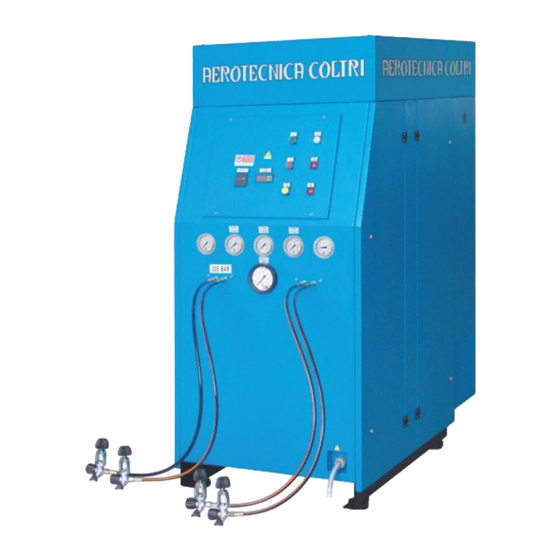
Page 29: Machine Parts
Cap.4 _ Technical data 4.1.9 - MACHINE PARTS Description: Frame Control panel Gauges Hoses Refill taps Condensate collection can Condensate collection recipient Electric motor Compressor 10 Oil filter 11 Air filter 12 Safety mesh 13 Anti-vibration devices 14 Cooling fan 15 Belt 16 Active carbon air filter 17 Active carbon air filter cartridge... -
Page 30: Chapter 5 - Handling And Installation
Cap.5 _ Handling and installation 5 - HANDLING AND INSTALLATION 5.1 - UNPACKING The MCH-36 compressor is sent fully assembled, but with the supplied flex hoses separate. The compressor is packed in a cardboard box; the latter is placed on a europallet to simplify handling and transport. -
Page 31: Air Intake Extension Connection
Cap.5 _ Handling and installation 5.3.2 - AIR INTAKE EXTENSION CONNECTION If the compressor is installed in an area without the necessary ventilation requisites described in section 5.3.1 “Positioning”, it will be necessary to install an air intake extension leading in from outdoors or a place with the cited ventilation requisites. -
Page 32: Electrical Connection
Cap.5 _ Handling and installation 5.3.4 - ELECTRICAL CONNECTION The compressor is delivered together with power lead and plug (4-pole, 32 A). To connect up to the power supply just insert the plug in the mains power socket. Check that the data on the compressor ID plate is compatible with mains power supply, especially as regards rated current and voltage. -
Page 33: Chapter 6 - Using The Compressor
Cap.6 _ Using the compressor 6 - USING THE COMPRESSOR 6.1 - PRELIMINARY CHECKS BEFORE USING FOR THE FIRST TIME The operator must check that the compressor is supplied with: - use and maintenance manual; - appendix to the use and maintenance manual; If the compressor is sold on the customer/user must provide the purchaser with a complete, undamaged use and maintenance manual. -
Page 34: Checks To Be Run At The Start Of Each Working Day
Cap.6 _ Using the compressor 6.2 - CHECKS TO BE RUN AT THE START OF EACH WORKING DAY Inspect the exterior of the compressor (couplings, pipes, pneumatic components etc.) and check for any oil leaks. 6.2.1 - LUBRICATING OIL LEVEL CHECK Check that the level of lubricating oil (a) is within acceptable limits (i.e. -
Page 35: Control Panel
Cap.6 _ Using the compressor 6.3 - CONTROL PANEL KEY: Power indicator light Oil pressure gauge Direction of rotation indicator light 10 1st stage pressure gauge Oil level warning light 11 2nd stage pressure gauge ON pushbutton 12 3rd stage pressure gauge Stop-emergency pushbutton 13 Working pressure gauge Manual condensate discharge pushbutton... -
Page 36: Direction Of Rotation Indicator Light
Cap.6 _ Using the compressor 6.3.2 - DIRECTION OF ROTATION INDICATOR LIGHT If the direction of rotation indicator light (2) comes on this means that the main power phases are inverted. To restore proper operation disconnect from the electrical power supply and invert two of the three phases on the main power lead plug. -
Page 37: Manual Condensate Discharge Pushbutton
WARNING: Temperature parameters must not be changed without prior authorisation from AEROTECNICA COLTRI S.r.l.: doing so will render the warranty null and void (where still valid). 6.3.8 - HOUR COUNTER The hour counter (8) indicates the hours of effective compressor operation: use this information to observe maintenance schedules. -
Page 38: 1St Stage Pressure Gauge
If pressure is not between 65 bar (940 PSI) and 80 bar (1200 PSI) switch off the compressor and contact AEROTECNICA COLTRI S.r.l. 6.3.13 - WORKING PRESSURE GAUGE The gauge (13) indicates air pressure as it exits the compressor. -
Page 39: Adjustable Automatic Shutdown Pressure Switch
Cap.6 _ Using the compressor 6.3.14 - ADJUSTABLE AUTOMATIC SHUTDOWN PRESSURE SWITCH The automatic shutdown pressure switch (14) determines the compressor shutdown pressure. The shutdown pressure can be set via the regulator (a) and displayed via the indicator (b). When the compressor reaches the set pressure it shuts down automatically. -
Page 40: Preliminary Tasks
Cap.6 _ Using the compressor 6.4 - PRELIMINARY TASKS 6.4.1 - SAFETY VALVE CHECKS Check that safety valves are working properly by starting the compressor with the end taps closed: this will raise circuit pressure fast and trip the valves when their pressure setting is reached. The valves are pre-adjusted to 225 bar (3200 PSI) or 330 bar (4700 PSI). -
Page 41: Automatic Condensate Discharge
Cap.6 _ Using the compressor 6.4.2 - AUTOMATIC CONDENSATE DISCHARGE The condensate gathered in the container (d) must be drained as described below every 5 working hours of the compressor. Insert the condensate drain pipe (a) in a collection can (b) and open the drain tap (c). The release of vaporised water with lubricating oil during bottle refill is normal: the quantity depends on the level of humidity in the air. - Page 42 Cap.6 _ Using the compressor To refill the bottles proceed as follows: - Fit the hose connector (a) to the bottle tap (b) - Screw in the fixing knob (c) until it is completely tightened - Check that the bleed tap (f) is closed by rotating it clockwise - Open the tap (d) by rotating it anticlockwise - Open the tap (e) by rotating it anticlockwise...
-
Page 43: Chapter 7 - Maintenance
Cap.7 _ Maintenance 7 - MAINTENANCE WARNING: Maintenance tasks must only be carried out by the AEROTECNICA COLTRI S.r.l. Customer Assistance Service or qualified personnel. DANGER: All maintenance tasks must be carried out with the compressor off and the power lead unplugged from the mains socket. -
Page 44: Scheduled Maintenance Table
Cap.7 _ Maintenance 7.4 - SCHEDULED MAINTENANCE TABLE Every Every Every 1000 3000 Maintenance 5 hours year (hours) (hours) (hours) (hours) Lubricating oil level check Automatic shutdown check Condensate container discharge Belt wear and tension Air intake filter Fitting/hose leak check Oil filter and oil change Separator filter element cleaning 1st –... -
Page 45: Checking And Changing The Lubricating Oil And Filter
Cap.7 _ Maintenance 7.6 - CHECKING AND CHANGING THE LUBRICATING OIL AND FILTER After putting the compressor into service the oil filter and the lubricating oil itself must be changed after the first 50 (fifty) working hours. Replacement of the filter and the lubricating oil must be done every 250 hours working hours or annually. IMPORTANT: The compressor must be placed on a solid surface with a tilt of no more than 5°. -
Page 46: Changing The Lubricating Oil And Filter
Cap.7 _ Maintenance 7.6.3 - CHANGING THE LUBRICATING OIL AND FILTER The lubricating oil must be changed every 250 wor- king hours or annually. Every time the lubricating oil is changed the oil filter must be changed too. To change the oil proceed as described: - position a recipient under the drain tap (a) so that the oil flows into the exhausted oil recipient (recipient capacity of at least 5 litres... -
Page 47: Changing The Intake Filter
Cap.7 _ Maintenance 7.7 - CHANGING THE INTAKE FILTER After putting the compressor into service the intake filter must be changed after the first 50 working hours. The air filter must then be changed every 250 working hours or annually. Every 50 working hours rotate the filtration cartridge inside the filter 90°. -
Page 48: Checking The Safety Valve
(observe the gauge) you can open the taps and pro- ceed with the refill. IMPORTANT: Should the safety valve fail to operate properly contact the AEROTECNICA COLTRI S.r.l. technical assistance service. 7.9 - TRANSMISSION BELTS Belt tension must be checked monthly. -
Page 49: Changing The Transmission Belts
- insert the second belt and carry out the same procedure described for the first belt. If belt tension is not correct contact the AEROTECNICA COLTRI S.r.l. technical assistance service. M C H - 3 6 Use and maintenance manual... -
Page 50: Condensate Discharge
Cap.7 _ Maintenance 7.10 - CONDENSATE DISCHARGE The condensate must be drained at the end of every working day. DANGER: Do not carry out these tasks if the compressor has only just shut down; wait for the com- pressor to cool. All maintenance work must be carried out with the compressor OFF and the power supply lead unplugged from the mains socket. -
Page 51: Active Carbon Filters / Molecular Sieve
Cap.7 _ Maintenance 7.11 - ACTIVE CARBON FILTERS / MOLECULAR SIEVE The active carbon filter must be replaced at intervals calculated on the basis of the characteristics of the environment in which the compressor is located. To calculate these intervals refer to the table below. The filter must nevertheless be replaced before the air becomes malodorous. - Page 52 Cap.7 _ Maintenance - remove the filter plug (c); - remove the active carbon filter cartridge (d) and replace it with a new one; - replace the O-ring (e) on the plug (c) every time the filter is changed; - close the filter and screw it on with the wrench (a).
-
Page 53: Changing The Flex Hoses
Cap.7 _ Maintenance 7.12 - CHANGING THE FLEX HOSES IMPORTANT: The hoses must be changed periodically (yearly or every 1000 hours) or when they show signs of abrasion/wear/damage. The bending radius of the hoses must not be less than 250 mm. DANGER: Do not carry out these tasks if the compressor has only just shut down;... -
Page 54: Chapter 8 - Storage
Cap.8 _ Storage 8 - STORAGE Should the compressor not be used, it must be stored in a dry sheltered area at an ambient temperature of between 0 °C and 40 °C. Store the compressor away from sources of heat, flames or explosive. 8.1 - STOPPING THE MACHINE FOR A BRIEF PERIOD If you do not intend to use the compressor for a brief period proceed with general cleaning. -
Page 55: Chapter 9 - Dismantling And Putting Out If Service
Cap.9 _ Dismantling and putting out if service 9 - DISMANTLING AND PUTTING OUT OF SERVICE Should you decide not to use the compressor or any of its parts any longer you must proceed with its dis- mantling and putting out of service. These tasks must be carried out in compliance with the standards in force. -
Page 56: Chapter 10 - Instructions For Emergency Situations
Cap.10 _ Instructions for emergency situations 10 - INSTRUCTIONS FOR EMERGENCY SITUATIONS 10.1 - FIRE In the event of fire use a CO extinguisher in compliance with the relevant standards in force. Contact the fire brigade. M C H - 3 6 Use and maintenance manual pag. -
Page 57: Chapter 11 - Maintenance Register
Cap.11 _ Maintenance register 11 - MAINTENANCE REGISTER Date Component Task and notes Signature M C H - 3 6 Use and maintenance manual pag. - Page 58 Cap.11 _ Maintenance register 11 - MAINTENANCE REGISTER Date Component Task and notes Signature M C H - 3 6 Use and maintenance manual pag.
- Page 59 Cap.11 _ Maintenance register 11 - MAINTENANCE REGISTER Date Component Task and notes Signature M C H - 3 6 Use and maintenance manual pag.
-
Page 60: Chapter 12 - Notes
Cap.12 _ Notes 12 - NOTES M C H - 3 6 Use and maintenance manual pag. - Page 61 Cap.12 _ Notes 12 - NOTES M C H - 3 6 Use and maintenance manual pag.
- Page 62 Via Colli Storici, 177 25010 SAN MARTINO DELLA BATTAGLIA (BS) ITALY Tel. +39 030 9910301 Fax. +39 030 9910283 www.coltrisub.it www.coltrisub.com coltrisub@coltrisub.it w w w. c o l t r i s u b. c o m...
Need help?
Do you have a question about the MCH-36 and is the answer not in the manual?
Questions and answers