Table of Contents
Advertisement
Advertisement
Table of Contents

Related Manuals for Del Morino Levante


Summary of Contents for Del Morino Levante
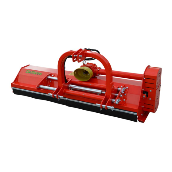
- Page 1 Del Morino srl , v.Caroni di Sotto 19, I-52033 Caprese Michelangelo AR Italy Ph: +39-575-791059 Fax: +39-575-791210 E.mail: export@del-morino.it http://www.del-morino.it MANUAL OF USE AND MAINTENANCE PROFESSIONAL FLAIL MOWER LEVANTE MODEL Levante-e-01 Manual of use and maintenance : Levante...
-
Page 2: Preface
PREFACE This manual is an integral part of the machine. It must always accompany the machine and be kept within reach of the operator. The enclosures mentioned are on integral part of this manual. The purpose of this manual. This manual gives information for the correct and safe use of the machine. The owner must read this manual carefully before work with the machine. -
Page 3: Description
DESCRIPTION UNCTION OF USE The machine according to the different tools can makes different functions like cut grass, cut up poles exc. The use of a technical constructive concept trended to the search of high performances, reduction of troubles and durability, improves the power/consumption ratio of the tractor thanks to the elasticity of the machine frame, to the tools shape, to the perfect rotor balancing and to many original technical solutions. -
Page 4: Technical Specifications
TECHNICAL SPECIFICATIONS Rotor MODEL r.p.m. AxBxC n° n° g/min Cm/Inch FIX HITCH 182x100 2-12 2380 160 F x100 208x100 2-12 1073 2380 190 F x100 234x100 2-12 1155 2380 220 F x100 260x100 2-12 1294 2240 250 F x100 HYDRAULIC SIDE SHIFT HITCH 400 mm 182x100 2-12 1122... -
Page 5: Safety Information
SAFETY INFORMATION GENERAL INSTRUCTIONS Work in daylight only. To prevent damage due to the launching of objects or parts of blades, before to start job be sure that any persons or animals should be in the radius of 50 meters from the machine. ... -
Page 6: Safety Signs On The Machine
SAFETY SIGNS ON THE MACHINE In this section, the safety signs on the machine are reproduced and explained. 1. Read the operator manual. 2. Disconnect the tractor key before maintenance and repair operations. 3. Stay at safety distance from blades when machine is moving. 1. -
Page 7: Cardan Shaft Length Checking
CARDAN SHAFT LENGTH CHECKING 1. After having linked up the machineto the third point, please check it is placed in a horizontal and central position in relation to the tractor using the adjustment devices. 2. Place the PTO shaft between the tractor' PTO and the machine's PTO. 3. -
Page 8: How To Shorten The Cardan Shaft
HOW TO SHORTEN THE CARDAN SHAFT Figure 1 1. Move the machine as close as possible to the tractor, by using an hydraulic lift. 2. Once in this position, stop the hydraulic lift and switch the engine off. 3. Separate the two parts of the PTO shaft. 4. -
Page 9: Instructions For Use
INSTRUCTIONS FOR USE EFORE BEGINNING WORK a) Adjust the slides as follows : 1. Unscrew the 2 screws "A" and “B” then take out them. 2. Set the position of the slide. 3. Insert again the screws "A" and "B" in place then lock them. 4. -
Page 10: To Beginning Work
b) Hook the machine to the tractor, operate as follows : 1. Remove the safety pins then take out the pins from the two lower connection points of the machine. 2. Plug in the raising tractor beams into the lower hitch points of the machine, plug in the pins, and lock with the safety pins. -
Page 11: Instructions For The Maintenance
INSTRUCTIONS FOR THE MAINTENANCE On diagram "A" the maintenances are indicated with their terms to effect on the machine. Not follow the scheduled terms can compromise the functionality of the machine and in this case the warranty is not applicable. DIAGRAM “A”... -
Page 12: Greasing
1. G REASING At the scheduled time on diagram "A", grease the 7 points "A" “B”, “C”,”D”, “E”, “F”. Greasing point is equipped with greaser HYDRAULIC TYPE MODEL "A" UNI 7663. To greasing use only MULTIFUNCTIONAL GREASE LITHIUM BASED Type NLGI 2. IL CHECK - OIL REPLACEMENT IN GEAR BOX At the scheduled time on diagram "A", check or replace oil into gear box. -
Page 13: Tools Replacement
OOLS REPLACEMENT a) To change tools, operate as follow : 1. Unscrew the nut then take out the screw “C”. 2. Take out knifes “A” and "B" with spacers. If tool is an hummer "A" there are no spacers. 3. Assemble the new tool. 4. - Page 14 b) To replace the drive belts, procced as follows : 1. Disassemble the cover “H” unscrewing the 7 screws “I”. 2. Unscrew the lock nut “F”, loosen the 2 screws "L" and unscrew completely the adjusting screw “G” 3. Take off the 4 worn belts “E”. Attention: to avoid tensions problems, the belts must be replaced with original ones, noticing the features from the SPARE PART LIST.
-
Page 15: Assembling Of The Additiona Lsteel Skids
5. ASSEMBLING OF THE ADDITIONAL STEEL SKIDS a) To assemble the additional steel skids proceed as follows: Close the additional skid “D” to the slide “E” Insert the 2 screws “A” in the holes Tighten screw “A” with nut ”B” and washer “C” Make again the same operation from the other side of the machine. -
Page 16: Assembling Of The 1000 R.p.m. Kit
6. ASSEMBLING OF THE 1000 R.P.M. KIT In order to assemble the transformation kit from 540 rpm to 1000 rpm it is necessary to disassemble the transmission and replace some components. a) To disassemble the transmission follow the instructions below : Take off the cover “M”... -
Page 17: Assembling Of The Rear Roll Extension
7. ASSEMBLING OF THE REAR ROLL EXTENSION a) To apply the rear roll extension kit : Unscrew completely the 2 screws “A” removing nuts and washers Make the same operation on the other side of the machine Remove the roll “B” with the relating supports Assemble the right extension “F”... -
Page 18: Problems Solving
PROBLEMS SOLVING TROUBLES GROUNDS AND SOLUTIONS -Rotor not balanced – Enquire a dealer. -Loss of one or more tools – Replace. Abnormal vibrations -Damaged bearings – Replace. -Damaged tools – Replace. Uneven or unsatisfactory cut -Tools choice not good – Change with another type. -
Page 19: Transport
TRANSPORT Except when working, moving the machine takes place when the machine is standing still and the transmission is disconnected. <Important>: keep speed low avoiding holes and ground roughness. <Important>: Before begin the movements always make sure that the safety hooks be in position. <Note when on the road, obey existing traffic laws. -
Page 20: Work And Maintenance Sheet
WORK AND MAINTENANCE SHEET Every user should register on this sheet the facts about the life of the machine (both work and maintenance), so as to attest its conditions. DATE WORKING HOUR MAINTENANCE NOTE OPERATOR... - Page 21 SPARE PARTS AND ACCESSORIES...
-
Page 22: Sheets
SHEETS... -
Page 23: Mechanisms
MECHANISMS... -
Page 24: Point Hitch
III POINT HITCH... -
Page 25: Hydraulic Plant
HYDRAULIC PLANT... -
Page 26: Table Of Contents
INDEX PREFACE .................................. 2 DESCRIPTION ................................3 FUNCTION OF USE ............................... 3 PERFORMANCES ..............................3 PERFORMANCES LIMIT ............................3 STANDARD EQUIPMENTS ........................... 3 VARIANT & OPTIONS ............................3 TECHNICAL SPECIFICATIONS ..........................4 SAFETY INFORMATION ............................5 GENERAL INSTRUCTIONS ..........................5 SAFETY RESTRICTIONS ............................ - Page 27 : Dott. A. Del Morino, Via Caroni di Sotto 19, 52033 Caprese Michelangelo Arezzo Italy. Dépositaire du dossier technique : Dott. A. Del Morino, Via Caroni di Sotto 19, 52033 Caprese Michelangelo Arezzo Italy. Verwalter der technischen Unterlagen : Dott. A. Del Morino, Via Caroni di Sotto 19, 52033 Caprese Michelangelo Arezzo Italy.
Need help?
Do you have a question about the Levante and is the answer not in the manual?
Questions and answers