
Subscribe to Our Youtube Channel
Related Manuals for Del Morino DISCO KNIFE


Summary of Contents for Del Morino DISCO KNIFE
- Page 1 USE AND MAINTENANCE MANUAL FLAIL MOWER DISCO Disco-EN-R2023.02.docx USE AND MAINTENANCE MANUAL: DISCO...
- Page 2 Caroni di Sotto, 19 - I-52033 Caprese Michelangelo AR Italy Phone: +39-575-791059 - Fax: +39-575-791210 Website: http://www.delmorino.it – e-mail: export@delmorino.it All rights reserved Printed in Italy DEL MORINO SRL thanks you for choosing us and for confidence in the quality of our implements.
- Page 3 PREFACE This manual is an integral part of the implement It must always come with the implement and be at user’s disposal. All attachments are integral part of the manual. The purpose of this manual This manual provides information for the correct and safe use of the implement. The owner must read this manual carefully before working with the implement.
-
Page 4: Field Of Use
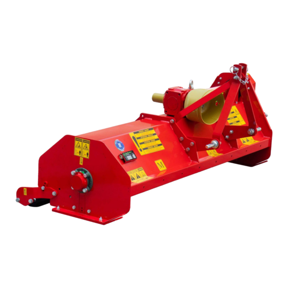
DESCRIZIONE DESCRIPTION FIELD OF USE The machine thanks to the III point hitch and to the different tools can make different functions like cut grass, cut up poles etc. The use of a technical constructive concept aimed at reaching high performances, reliability and durability improves the efficiency in terms of power/tractor consumption ratio, thanks to the rigidity of the implement frame, the shape of the tools, the perfect dynamic balancing of the rotor and many others original technical solutions. -
Page 5: Technical Features
SPECIFICHE TECNICHE TECHNICAL FEATURES SPECIFICATIONS PER MODEL Working Rotor Model Type Version Power Weight Dimensions A x B x H N° Tools width n° g/min 12-20 9-15 107x60x60 43x24x24 2410 FONT 15-30 12-23 107x60x60 43x24x24 2410 15-25 12-19 120x60x60 48x24x24 2410 FONT 15-40... -
Page 6: Safety Information
SAFETY INFORMATION SAFETY INFORMATION GENERAL REQUIREMENTS CAUTION: To prevent damage due to the launch of objects or parts of blades, before starting to work, be sure that no persons or animals are within a radius of 50 meters (164 ft) from the implement. - Page 7 SAFETY LABELS ON THE IMPLEMENT SAFETY LABELS ON THE IMPLEMENT In this section, the safety labels of the implement are reproduced and explained. Pic. 1 Legend Read the manual. Remove the key from the ignition of the tractor before performing maintenance or repairs. Stay at a safe distance from the PTO shaft.
-
Page 8: Pto Shaft
PTO SHAFT PTO SHAFT CHECK THE LENGTH OF THE PTO SHAFT Pic. 2 Connect the implement to the 3-point hitch and adjust it so that it is level and centered on the tractor. Insert the PTO shaft between the PTO of the tractor and the implement. Verify that the length of the PTO shaft is correct. - Page 9 PTO SHAFT HOW TO SHORTEN THE PTO SHAFT Pic. 3 Using the hydraulic lift, bring the implement as close as possible to the tractor. In this position, block the lift and turn off the engine. Pull the two parts of the PTO shaft completely apart. Attach the female semi-cardan (tube with larger diameter) into the PTO.
- Page 10 FIRST ASSEMBLY INSTRUCTIONS FIRST ASSEMBLY INSTRUCTIONS DISCO FONT / DISCO ALU Once you took the implement from the packaging, assemble the 3-point hitch as shown in picture M.2. Pic. M.1 Assemble the 2 tie-rods [A] using bolts [B] without tightening the nuts. Assemble the two brackets (D) using bolts ( C) without tightening the nuts.
-
Page 11: Before Starting To Work
INSTRUCTIONS FOR USE INSTRUCTIONS FOR USE BEFORE STARTING TO WORK • To attach the machine to the tractor, operate as follows: Remove the safety pins from the two lower connection points of the implement. Plug in the raising tractor beams into the lower connection points of the implement and lock with the safety pins. -
Page 12: At The End Of The Work
INSTRUCTIONS FOR USE START WORKING • Make sure that there is no one within a radius of 50 meters (164 ft) around the implement. • Insert the PTO and increase the rotation speed gradually to its normal speed. • Lower the implement until the rear roller touches the ground. •... -
Page 13: Maintenance Instructions
MAINTENANCE INSTRUCTIONS MAINTENANCE INSTRUCTIONS Maintenance operations and their corresponding intervals are listed in sheet “A”. Not following the schedule maintenance intervals jeopardizes the proper functioning of the implement, thus voiding the guarantee. SHEET “A” SCHEDULED MAINTENANCE END OF THE BEGINNING END OF FIRST USE AFTER 10 H. -
Page 14: Oil Level - Oil Change
MAINTENANCE INSTRUCTIONS 1. GREASING Grease the points “A,” “B”, “C”, ”D” as indicated in sheet “A”. Greasing points are equipped with a HYDRAULIC GREASER MODEL “A” UNI 7663. Use only MULTIFUNCTIONAL LITHIUM-BASED OIL TYPE NLGI 2. Pic. 6 2. OIL LEVEL - OIL CHANGE At the deadlines indicated in sheet “A”, check the level or replace the oil in the gearbox. -
Page 15: Tools Replacement
MAINTENANCE INSTRUCTIONS • To check the oil level in the aluminium gearbox, proceed as follows: With the machine on a level ground, unscrew the cap “TR” and check that the oil level is touching the edge of the hole. If the level is OK, tighten the cap “TR” carefully. If the level is LOW, fill with oil- When the level is OK, tight the cap “TR”... - Page 16 MAINTENANCE INSTRUCTIONS 4. ADJUSTMENT AND REPLACEMENT OF THE TRANSMISSION BELTS • To adjust the transmission belts tension, proceed as follows: Remove the belt cover “A” unscrewing the 12 screws “B”. Unscrew the locknut “C”, tighten the screw “D” to stretch the belts or unscrew it to loose them. The tension is correct when you pull the sides of the belts with your thumb and they give away to a few millimeters.
- Page 17 MAINTENANCE INSTRUCTIONS 5. MOUNTING THE ADDITIONAL STEEL SKIDS • To mount the skids kit, proceed as follows: Accost the skid “A” to the skid “B”. Insert the 2 screws “C” in the appropriate holes. Tighten the screws “C” with the nuts “E” and the washers “D”. Repeat the same operation on the other side of the machine.
- Page 18 MAINTENANCE INSTRUCTIONS QUICK HITCH KIT ASSEMBLY The machine is shipped with the standard hitch suitable for tractors with category I 3-point hydraulic lift, a "quick hitch kit" is supplied with the machine to make the hitch suitable for tractors equipped with a "Quick Attaching Coupler".
- Page 19 MAINTENANCE INSTRUCTIONS 1. Insert the bushing "BI" onto the lower right pin "PI" and then lock it with the spring pin "SE". 2. Repeat step 1 with the left lower pin "PI". 3. Insert the bushing "BS" into the III° point, then insert the bolt "BU" and tighten the nut. Quick Hitch Attack...
-
Page 20: Troubleshooting
TROUBLESHOOTING TROUBLESHOOTING MALFUNCTIONS CAUSE SOLUTION 1) Unbalanced rotor. 1) Contact the dealer. Abnormal vibrations 2) Loss of one or more tools. 2) Replace missing tools. 3) Worn out bearings. 3) Replace worn out bearings. 1) Worn out tools. 1) Replace worn out tools. Irregular or unsatisfactory cutting 2) Incorrect choice of tools. -
Page 21: Various Information
VARIOUS INFORMATION VARIOUS INFORMATION TRANSPORT Outside its normal field of use, the implement must be moved with the PTO disengaged. IMPORTANT: proceed at moderate speed avoiding holes and rough surfaces. NOTE: on the road, abide by the traffic laws. Attach labels to the rear side of the implement indicating the contour of the implement. -
Page 22: Work And Maintenance Sheet
WORK AND MAINTENANCE SHEET WORK AND MAINTENANCE SHEET Every user should register the facts about the history of the implement (both operation and maintenance) on this sheet, to verify its conditions. HOURS OF DATE MAINTENANCE NOTES OPERATOR OPERATION... - Page 23 GENERAL INDEX GENERAL INDEX PREFACE ..........................2 DESCRIPTION ........................4 FIELD OF USE ............................. 4 PERFORMANCES ..........................4 PERFORMANCE LIMITS ........................4 STANDARD FEATURES ........................4 VARIANTS & ACCESSORIES ......................4 TECHNICAL FEATURES ....................5 SPECIFICATIONS PER MODEL ......................5 SAFETY INFORMATION ....................
Need help?
Do you have a question about the DISCO KNIFE and is the answer not in the manual?
Questions and answers