Table of Contents
Advertisement
Advertisement
Table of Contents

Subscribe to Our Youtube Channel
Related Manuals for Del Morino OMEGA 11


Summary of Contents for Del Morino OMEGA 11
- Page 12 Del Morino srl , v.Caroni di Sotto 19, I-52033 Caprese Michelangelo AR Italy Ph: +39-575-791059 Fax: +39-575-791210 E.mail: export@del-morino.it http://www.del-morino.it USE AND MAINTENANCE MANUAL OMEGA LEFT RIGHT REAR Omega-e-04 Use and maintenance manual : OMEGA...
- Page 13 PREFACE This manual is an integral part of the machine. It must always accompany the machine and be kept within reach of the operator. The enclosures mentioned are on integral part of this manual. The purpose of this manual. This manual gives information for the correct and safe use of the machine. The owner must read this manual carefully before work with the machine.
-
Page 14: Standard Equipment
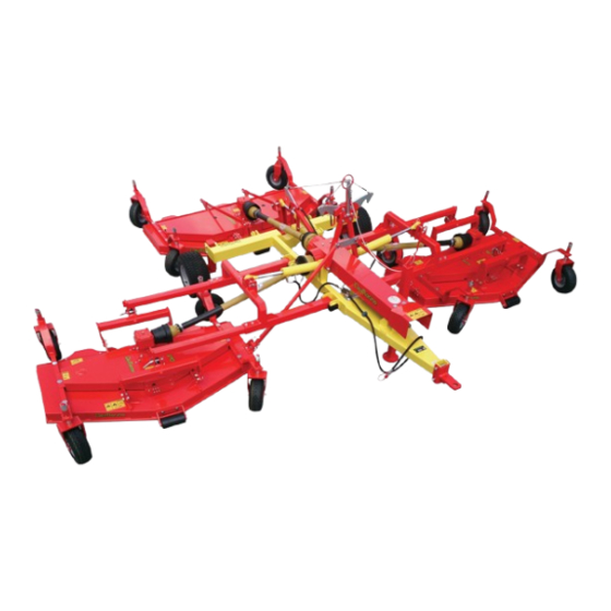
DESCRIPTION UNCTION OF USE The machine gives grass a professional cut. The grass is first raised, then cut with precision and discharged in the rear side along the width of discharge. It perfects any preliminary cut. The machine is formed by 3 cutting components; each one moves in the soil with 4 pivotal wheels; each component is free in the movements to adjust itself to the soil. -
Page 15: Technical Specifications
SAFETY DEVICES The machine is equipped with a lock device with a manual unhooking that keep the casual descent of the 3 cutting components during the transport and maintenance operations. TECHNICAL SPECIFICATIONS RAW-HOOK OF THE TRACTOR The diameter of the hitch pin must not be less than 30 mm., the pin must be produced in C 40 steel or similar and must be equipped to the extremities of a hole to apply the safety spring pin. -
Page 16: Safety Informations
SAFETY INFORMATIONS ENERAL REGULATIONS Only work in daylight. The machine must not be used near people, especially children or animals. Wear long pants and heavy shoes. The protections are integral part of the machine: always work with the protections. Make sure that the 4 wheels of all components be adjusted to the same cutting height. Pay attention to the soil: make sure that are not stones, sticks, iron wires, etc…... -
Page 17: Safety Signs On The Machine
SAFETY SIGNS ON THE MACHINE In this section, the safety signs on the machine are reproduced and explained. 1. Read the operator manual. 2. Disconnect the tractor key before maintenance and repair operations. 3. Stay at safety distance from blades when machine is moving. 1. -
Page 18: Assembling Instructions
ASSEMBLING INSTRUCTIONS PARTS LIST POS. DESCRIPTION Q.TY’ 1 MAIN FRAME 2 REAR HUB 3 REAR WHEEL 4 LIFTING JACK 5 RIGHT SIDE CONNECTION FRAME 6 LEFT SIDE CONNECTION FRAME 7 REAR CUTTING COMPONENT 8 RIGHT SIDE CUTTING COMPONENT 9 LEFT SIDE CUTTING COMPONENT 10 CROSS BAR WHEEL CASE 11 MOWER WHEEL GROUP 13 CASING... - Page 21 AIN FRAME "1"ASSEMBLING Insert the REAR HUB "2" in the fitting fork found in the rear right side from the MAIN FRAME "1", adjust it the height on POSITION 1 if the cutting components are equipped with rubber wheels, or in POSITION 2 if the cutting components are equipped with pneumatic tires (see TABLE "A"...
- Page 22 accordance with the height of the tractor draw-hook and to permit to the machine to work the most parallelly to the ground , insert the screws and lock the nuts. OUNTING RIGHT CUTTING COMPONENT "8" a) Insert the CROSS BAR WHEEL CASE "10" in the seat found on the right of the RIGHT CUTTING COMPONENTS "8", insert the screws and lock them with the nuts.
-
Page 23: Greasing And Lubrication
OUNTING REAR CUTTING COMPONENT ON MAIN FRAME a) Insert the hitches found on the front of the rear connecting frame. Insert the screws and lock them with the nuts. b) Insert the head holes of the REAR END STROKE ROD "17" into the forks found on the rear side of the rear connecting frame. -
Page 24: Before Beginning Work
INSRTRUCTION FOR USE EFORE BEGINNING WORK a) Ceck oil level in gear boxes . ( see page 17 point “4” ) b) Hook the machine to the tractor. c) Connect the hydraulic system of the machine to that of the tractor by means of the quick coupling (fast clutch). -
Page 25: T O Beginning Work
O BEGINNING WORK a) Keep people, animals and things at least 15 meters from the machine. Start the engine and lower the 3 cutting components as follows: b) Pull the cable to free the side safety hooks. Activate the hydraulic switch and wait until the 2 side cutting components are touching the ground. - Page 26 MAINTENANCE INSTRUCTIONS On diagram "A" the maintenances are indicated with their terms to effect on the machine. Not follow the scheduled terms can compromise the functionality of the machine and in this case the warranty is not applicable. DIAGRAM “A” SCHEDULED MAINTENANCE FIRST AFTER EACH...
- Page 27 RAME GREASING All the greasing points, both those situated and both centralized, are equipped with greaser HYDRAULIC TYPE MODEL “A” UNI 7663. To grease use only MULTIFUNCTIONAL GREASE LITHIUM BASED Type NLGI 2. Refer to the scheme, the greasing points are the points "A". Greasing operation must be made at the terms scheduled on diagram “A”.
- Page 28 OWERS GREASING All the greasing points, both those situated and both centralized, are equipped with greaser HYDRAULIC TYPE MODEL “A” UNI 7663. To grease use only MULTIFUNCTIONAL GREASE LITHIUM BASED Type NLGI 2. Refer to diagram, greasing points are points "C" one per each wheel, point "D" located on a bracket in front of gear box bracket.
- Page 29 ELTS ADJUSTING AND SUBSTITUTION To adjust the tension or substitute the trapezoidal transmission belts operate as follows : a) Remove the two upper protection of the cutting component unlocking the fixing screws. b) Unlock the 4 screws "A" and nut “B”. c) To substitute the belts, turn the screw "C"...
- Page 30 LADES SUBSTITUTION To substitute the blades or to make operations of sharpeness and/or balance,refering operate as follows: a) Bring mower in raised position and make sure that the transmission be disconnected. b) Take stopped the blade with one hand. c) Unscrew the stop ring nut "B". d) Remove the blade "A"...
-
Page 31: Problems Solving
PROBLEMS SOLVING TROUBLES GROUNDS AND SOLUTIONS -Damaged blade - Replace -Broken blade - Replace Abnormal vibrations -Not balanced blade - Balance -Damaged bearings – Change -Damaged hub - Change Uneven or unsatisfactory cut -Not sharp blade - Sharp... -
Page 32: Information On Demolition
TRANSPORT Except when working, moving the machine takes place when the machine is standing still and the transmission is disconnected. <Important>: keep speed low avoiding holes and ground roughness. <Important>: Before begin the movements always make sure that the safety hooks be in position. <Note when on the road, obey existing traffic laws. -
Page 33: Work And Maintenance Sheet
WORK AND MAINTENANCE SHEET Every user should register on this sheet the facts about the life of the machine (both work and maintenance), so as to attest its conditions. DATE WORKING MAITENANCE NOTE USER HOURS... -
Page 34: Spare Parts & Options
SPARE PARTS & OPTIONS...
Need help?
Do you have a question about the OMEGA 11 and is the answer not in the manual?
Questions and answers