Table of Contents
Advertisement
Quick Links
Advertisement
Table of Contents

Subscribe to Our Youtube Channel
Related Manuals for Denso QS20P-A


Summary of Contents for Denso QS20P-A
- Page 1 2D Code Scanner AC Adapter Driven QS20P-A User's Manual...
- Page 2 DENSO WAVE cannot be responsible for any patent or other intellectual property right infringement(s) or violation(s) which arise from (i) the use of DENSO WAVE's product(s) in connection or in combination with other component(s), product(s), data processing system(s) or equipment or software not supplied from DENSO WAVE;...
- Page 3 Preface Please READ through these operating instructions carefully. It will enable you to operate your QS20P-A correctly. After you have finished reading the instructions, keep this manual handy for speedy reference.
-
Page 4: Safety Precautions
Be sure to observe all these safety precautions. Please READ through this manual carefully. It will enable you to use the QS20P-A correctly. Always keep this manual nearby for speedy reference. Strict observance of these warning and caution indications are a MUST for preventing accidents which could result in bodily injury and substantial property damage. - Page 5 Failure to do so could cause fire or electrical shock. • If you drop the QS20P-A so that it fails to operate or its housing gets damaged, immediately turn off the power, unplug the AC adapter from the wall socket, and contact your nearest dealer.
- Page 6 Moisture or dust will get into the QS20P-A, resulting in malfunc- tion, fire or electrical shock. • Do not place the QS20P-A anyplace where it may be subjected to oily smoke or steam, e.g., near a cooking range or humidifier.
- Page 7 CAUTION • If you will not be using the QS20P-A for a long time, be sure to unplug the AC adapter from the wall socket for safety. Failure to do so could result in a fire. • Never cover or wrap up the QS20P-A or AC adapter in a cloth or blanket.
- Page 8 Failure to do so could result in a fire or electrical shock. • Keep the QS20P-A away from water, dust or dirt. Use of the QS20P-A after water, dust or dirt gets into it will emit smoke or cause fire. Turn off the power, unplug the AC adapter from the wall socket, and contact your nearest dealer.
-
Page 9: Proper Care Of Qs20P-A And Its Accessories
• If the QS20P-A or its accessories become smudged, moisten a soft cloth with neutral detergent diluted with water and wring it out thoroughly. Wipe the QS20P-A or its accessories with the cloth and then go over it again with a dry cloth. -
Page 10: Fcc Regulations
FCC Regulations This device complies with Part 15 of the FCC Rules. Operation is subject to the following two conditions: this device may not cause harmful interference, and this device must accept any interference received, including interference that may cause undesired operation. NOTE: This equipment has been tested and found to comply with the limits for a Class A digital device, pursuant to Part 15 of the FCC Rules. -
Page 11: Table Of Contents
Content Overviews Preface ........................SAFETY PRECAUTIONS ..................PROPER CARE OF QS20P-A AND ITS ACCESSORIES ........vii FCC Regulations ...................... viii Canadian Interference-Causing Equipment Regulations ........viii Chapter 1. Components in Package ..............Chapter 2. Names and Functions ................. Chapter 3. Preparation .................. -
Page 13: Chapter 1. Components In Package
Chapter 1. Components in Package • QS20P-A • User’s manual (this book) 2D Code Scanner AC Adapter Driven QS20P-A User's Manual... -
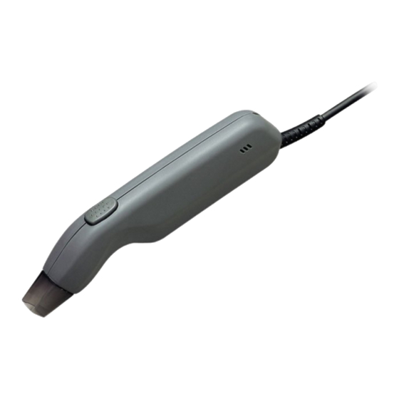
Page 14: Chapter 2. Names And Functions
Indicator LED Scanning window Illuminates in green when the Bring this window to a QR QS20P-A has read the QR code code to be scanned. successfully. Interface connector Via this connector, the QS20P-A DC power jack exchanges data with the host computer. -
Page 15: Chapter 3. Preparation
Chapter 6). You may modify those defaults by using the QR-coded parameter menu given in Chapter 7. Settings made from the QR-coded parameter menu will be stored in the memory of the QS20P-A, so they will be retained even after the QS20P-A power is turned off. -
Page 16: Chapter 4. Scanning Codes
Label Target code • If the QS20P-A fails to read due to specular effects or other factors, change the scanning angle of the scanning window or the distance from codes, and try it again. (Specular effects occur when the reflection of the light from the target code becomes excessively strong. - Page 17 • Disabling reading of unnecessary types of codes may increase the scan- ning speed. NOTE Before reading labels, clean them if stained. Avoid using the QS20P-A in direct sunlight. The QS20P-A might fail to read NOTE correctly.
-
Page 18: Chapter 5. Features
Chapter 5. Features Scanning If you press the trigger switch, the QS20P-A will turn the illumination LED on and become ready to scan. It will take approx. one second to make the QS20P-A ready for scan after depression of the trigger switch. Bringing the scanning window into contact with a target code will cause the QS20P-A to read the QR code and send it to the connected PC or external equipment automatically. - Page 19 When reading split QR codes, the QS20P-A beeps in a different way from usual. That is, when the QS20P-A reads the first split code, it beeps twice and enters the split code scanning mode. After that, each time it reads the subsequent split code, it beeps once.
- Page 20 Up to 8 kilobytes of data transferable in Edit mode In Edit mode, QS20P-A can read split codes of up to 8-kilobyte data, store and edit them, and then transfer the restored data to the PC. If a restored code contains data exceeding 8 kilobytes, the QS20P-A will cause a reading error and clear the restored data.
-
Page 21: Chapter 6. Parameters And Defaults
Chapter 6. Parameters and Defaults The table below lists the parameters and their default values. Note that the defaults given below are values preset when the QS20P-A leaves the factory. Some of the communications parameters and reading mode settings may have been modified by dealers according to your needs. - Page 22 Indicator LED Disabled Enabled √ Powering-off timer 1 minute 3 minutes √ 5 minutes 10 minutes 30 minutes Disabled RS-232C driver when the On standby √ QS20P-A is in standby In operation mode* * Some models do not support this parameter.
-
Page 23: Chapter 7. Qr-Coded Parameter Menu
Scan the "End setting" code in the menu control. This stores new settings in the memory and completes the parameter change procedure. The QS20P-A will become ready to scan. If you turn off the power, those new settings will be retained. - Page 24 Menu control "Start setting" (When the "White code on black background" is selected) "Cancel" "Defaults" "End setting" Communications procedure "Non-acknowledge "ACK/NAK mode" mode" (default)
- Page 25 Communications conditions CTS control Disabled (default) Enabled Transmission rate "4800 bps" "9600 bps" "19200 bps" "38400 bps" (default) "57600 bps" "115200 bps" Character length "7 bits" "8 bits” (default)
- Page 26 Parity check "No" (default) "Even parity" "Odd parity" Stop bit length "1 bit" (default) "2 bits" Transmission format Header "None" (default) "STX"...
- Page 27 Terminator "ETX" "CR" (default) "LF" "CR LF" Transmission of code ID mark "Disabled" (default) "Enabled" Transmission of no. of digits "Disabled" (default) "Enabled"...
- Page 28 Transmission of BCC "Disabled" (default) "Enabled" Reading modes QR code model (to be scanned) Model 1 Model 2 MicroQR Model 1 and Model 1, Model 2, Model 2 and MicroQR (default) Reading black-and-white inverted QR codes "Black code "White code on white on black background"...
- Page 29 Edit/Non-edit mode for split QR codes ("Structured Append") "Edit mode" "Non-edit mode" (default) Reading Data Matrix "Disabled" "Enabled" (default) Other settings Trigger switch control "Auto-off mode" "Alternate (default) switching mode" "Momentary "Continuous switching mode" reading mode"...
- Page 30 Beeper control "Disabled" "Enabled" (default) Beeper volume Medium High (defaults) Indicator LED "Disabled" "Enabled" (default)
- Page 31 Powering-off timer 1 minute 3 minutes 5 minutes (default) 10 minutes 30 minute Disabled RS-232C driver when the QS20P-A is in standby mode On standby In operation (default)
-
Page 32: Chapter 8. Communications
Chapter 8. Communications The QS20P-A communicates with the connected PC or external equipment in accordance with the RS-232C. You may set various communications conditions by scanning QR-coded parameters printed in Chapter 7. Communications flow You may select either the non-acknowledge mode or the ACK/NAK mode. - Page 33 ACK/NAK mode Start * You may enable or disable the Beeps when the QS20P-A beeper and the CTS control by has read a code. using the QR-coded parameter menu given in Chapter 7. Initializes the timer. CTS High? Transfers a single 2 seconds elapsed? character.
- Page 34 If not specified as binary codes, all data will be treated as ASCII codes. Listed below are port settings you can select. If data contains double-byte Japanese Kanji or binary data when the character length is set to 7 bits, the QS20P-A will ignore the MSB.
- Page 35 • QR Code All data read NOTE: If the QS20P-A reads split QR codes in Non-edit mode, it will transfer not only the read data but the ordinal ID number (a single byte in hex.) assigned to the split code, the number of splits (a single byte in hex.), and parity (double bytes in hex.).
-
Page 36: Appendix. Specifications
Appendix. Specifications A1. QS20P-A External dimensions (W x D x H) (Bore: 8 mm) 20 x 162 x 43 mm (0.79 x 6.38 x 1.69 inches) (Bore: 11 mm) 20 x 169 x 43 mm (0.79 x 6.65 x 1.69 inches) Weight Approx. -
Page 37: A2. Interface Requirements
Receive data Input Signal ground — CS (CTS) Ready to send Input Wiring example Shown below is an example of wiring the QS20P-A up to the PC. QS20P-A RD 2 2 SD 3 RD SD 3 SG 5 5 SG... - Page 38 Interface circuits Output circuit Input circuit RXD, CTS RS-232C LEVEL RS-232C LEVEL Voltage polarity Logical value Control level 0 (space) 1 (mark)
- Page 39 The purpose of this manual is to provide accurate information in the handling and operating of the QS20P-A. Please feel free to send your comments regard- ing any errors or omissions you may have found, or any suggestions you may...
Need help?
Do you have a question about the QS20P-A and is the answer not in the manual?
Questions and answers