Table of Contents
Advertisement
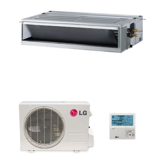
INSTALLATION MANUAL
AIR
CONDITIONER
Please read this installation manual completely before installing the product.
Installation work must be performed in accordance with the national wiring standards by
authorized personnel only.
Please retain this installation manual for future reference after reading it thoroughly.
Ceilling Concealed Duct
Original instruction (R32)
[Representative] LG Electronics Inc. EU Representative :
LG Electronics European Shared Service Center B.V.
Krijgsman 1, 1186 DM Amstelveen, The Netherlands
[Manufacturer] LG Electronics Inc. Changwon 2nd factory 84, Wanam-ro,
Seongsan-gu, Changwon-si, Gyeongsangnam-do, KOREA
P/NO : MFL67939930
Copyright © 2017 - 2018 LG Electronics Inc. All Rights Reserved.
www.lg.com
Advertisement
Table of Contents

Related Manuals for LG CL09R.N20


Summary of Contents for LG CL09R.N20
- Page 1 LG Electronics European Shared Service Center B.V. Krijgsman 1, 1186 DM Amstelveen, The Netherlands [Manufacturer] LG Electronics Inc. Changwon 2nd factory 84, Wanam-ro, Seongsan-gu, Changwon-si, Gyeongsangnam-do, KOREA www.lg.com P/NO : MFL67939930 Copyright © 2017 - 2018 LG Electronics Inc. All Rights Reserved.
-
Page 2: Model Designation
MODEL DESIGNATION MODEL DESIGNATION Airborne Noise Emission The A-weighted sound pressure emitted by Product information this product is below 70 dB. ** The noise level can vary depending on the - Product Name : Air conditioner site. - Model Name : The figures quoted are emission level and are not necessarily safe working levels. -
Page 3: Tips For Saving Energy
TIPS FOR SAVING ENERGY TIPS FOR SAVING ENERGY Here are some tips that will help you minimize the power consumption when you use the air conditioner. You can use your air conditioner more efficiently by referring to the instructions below: •... -
Page 4: Important Safety Instructions
IMPORTANT SAFETY INSTRUCTIONS IMPORTANT SAFETY INSTRUCTIONS Read the precautions in this manual This appliance is filled with carefully before operating the unit. flammable refrigerant (R32) This symbol indicates that a service This symbol indicates that the personnel should be handling this Operation Manual should be read equipment with reference to the carefully. - Page 5 IMPORTANT SAFETY INSTRUCTIONS Installation • Always perform grounding. - Otherwise, it may cause electrical shock. • Don’t use a power cord, a plug or a loose socket which is damaged. - Otherwise, it may cause a fire or electrical shock. •...
- Page 6 IMPORTANT SAFETY INSTRUCTIONS • Keep any required ventilation openings clear of obstruction. • The appliance shall be stored in a well-ventilated area where the room size corresponds to the room area as specified for operation. • Refrigerant tubing shall be protected or enclosed to avoid damage. •...
- Page 7 IMPORTANT SAFETY INSTRUCTIONS electric shock and damage. • Never touch the metal parts of the unit when removing the filter. - They are sharp and may cause injury. • Do not step on the indoor/outdoor unit and do not put anything on it.
- Page 8 IMPORTANT SAFETY INSTRUCTIONS product. - Otherwise, it may cause the failure of product. • Keep level parallel in installing the product. - Otherwise, it may cause vibration or water leakage. • Any person who is involved with working on or breaking into a refrigerant circuit should hold a current valid certificate from an industry-accredited assessment authority, which authorises their competence to handle refrigerants safely in accordance with an...
-
Page 9: Table Of Contents
TABLE OF CONTENTS TABLE OF CONTENTS MODEL DESIGNATION TIPS FOR SAVING ENERGY IMPORTANT SAFETY INSTRUCTIONS INSTALLATION PLACES THE INDOOR UNIT INSTALLATION Position of suspension Bolt Wiring Connection Flaring Work REMOTE CONTROLLER INSTALLATION Wired remote controller installation OPTIONAL OPERATION Installer Setting -Test Run Mode Installer Setting - Setting Address of Central Control Installer Setting -Thermistor Installer Setting -Ceiling Height Selection... -
Page 10: Installation Places
INSTALLATION PLACES INSTALLATION PLACES Install the air conditioner in the location that satisfies the following conditions. - The place shall easily bear a load exceeding four times the indoor unit’s weight. - The place shall be able to inspect the unit as the figure. - The place where the unit shall be leveled. - Page 11 INSTALLATION PLACES Minimum floor area - The appliance shall be installed, operated and stored in a room with a floor area larger than the mini- mum area. - Use the graph of table to determine the minimum area. Amin (m Floor standing Wall mounted Ceiling mounted...
-
Page 12: The Indoor Unit Installation
THE INDOOR UNIT INSTALLATION THE INDOOR UNIT INSTALLATION Position of suspension Bolt Ceiling Concealed Duct – Mid Static - Apply a joint-canvas between the unit and duct to absorb unnecessary vibration. - Apply a filter Accessory at air return hole. Ceiling Concealed Duct –... - Page 13 THE INDOOR UNIT INSTALLATION - Select and mark the position for fixing bolts Install the unit leaning to a drainage hole side and piping hole. as a figure for easy water drainage. - Decide the position for fixing bolts slightly tilted to the drain direction after considering Position of console Bolt the direction of drain hose.
- Page 14 THE INDOOR UNIT INSTALLATION - Insert the set anchor and washer onto the CAUTION suspension bolts for locking the suspension bolts on the ceiling. 1. Install declination of the indoor unit is - Mount the suspension bolts to the set very important for the drain of the duct anchor firmly.
-
Page 15: Wiring Connection
THE INDOOR UNIT INSTALLATION HEAT INSULATION 300mm or less 300mm or less 300mm or less - Use the heat insulation material for the 1 -1.5m refrigerant piping which has an excellent heat-resistance (over 120°C). - Precautions in high humidity circumstance: This air conditioner has been tested accord- Drain raising pipe ing to the "KS Standard Conditions with Mist"... - Page 16 THE INDOOR UNIT INSTALLATION Precautions when laying power CAUTION wiring The connecting cable connected to the Use round pressure terminals for connections indoor and outdoor unit should be com- to the power terminal block. plied with the following specifications (This equipment shall be provided with a Round pressure terminal cord set complying with the national regu- lation).
-
Page 17: Flaring Work
THE INDOOR UNIT INSTALLATION Flaring Work Putting nut on Main cause for gas leakage is due to defect of - Remove flare nuts attached to indoor and flaring work. Carry out correct flaring work in outdoor unit, then put them on pipe/tube the following procedure. - Page 18 THE INDOOR UNIT INSTALLATION CAUTION Check Compare the flared work with the figure • When mechanical connectors are reused indoors, sealing parts shall be renewed. If a flared section is defective, cut it off and do flaring work again. • When flared joints are reused indoors, the flare part shall be re-fabricated.
- Page 19 THE INDOOR UNIT INSTALLATION Set the tubing cutting line upward. Wrap the area which accommodates the rear piping housing section with vinyl tape. Cutting Line Cutting Line Gas Pipe Liquid Pipe Good Case Bad Case * Tubing cutting line have to be upward. Indoor unit pipe Connection pipe Vinyl tape (wide)
-
Page 20: Remote Controller Installation
REMOTE CONTROLLER INSTALLATION REMOTE CONTROLLER INSTALLATION Please fix tightly using provided screw after placing remote controller setup board on the place where you like to setup. - Please set it up not to bend because poor setup could take place if setup board bends. Please set up remote controller board fit to the reclamation box if there is a reclamation box. - Page 21 REMOTE CONTROLLER INSTALLATION Please fix remote controller upper part <Connecting order> into the setup board attached to the sur- face of the wall, as the picture below, and then, connect with setup board by press- ing lower part. Wall Wall Side Side - Please connect not to make a gap at the remote...
-
Page 22: Wired Remote Controller Installation
REMOTE CONTROLLER INSTALLATION Wired remote controller installation Since the room temperature sensor is in the remote controller, the remote controller box should be installed in a place away from direct sunlight, high humidity and direct supply of cold air to maintain proper space temperature. -
Page 23: Optional Operation
OPTIONAL OPERATION OPTIONAL OPERATION Installer Setting -Test Run Mode After installing the product, you must run a Test Run mode. For details related to this operation, refer to the product manual. If pressing button long for 3 seconds, it enters into remote controller setter setup mode. -
Page 24: Installer Setting - Setting Address Of Central Control
OPTIONAL OPERATION Installer Setting - Setting Address of Central Control It's the function to use for connecting central control. Please refer to central controller manual for the details If pressing button long for 3 seconds, it enters into remote controller setter setup mode. -
Page 25: Installer Setting -Thermistor
OPTIONAL OPERATION Installer Setting -Thermistor If pressing button long for 3 seconds, it enters into remote controller setter setup mode. - If pressing once shortly, it enters into user setup mode. Please press more than 3 seconds for sure. If moving to room temperature perception sensor selection menu by pressing button, it indicates as picture below. -
Page 26: Installer Setting -Ceiling Height Selection
OPTIONAL OPERATION Installer Setting -Ceiling Height Selection This function is to adjust FAN Airflow rate according to ceilingheight (only cassette model) If pressing button long for 3 seconds, it enters into remote controller setter setup mode. - If pressing once shortly, it enters into user setup mode. -
Page 27: Installer Setting-Group Setting
OPTIONAL OPERATION Installer Setting-Group Setting It is a function for settings in group control, or 2-remote controller control. If pressing button long for 3 seconds, it enters into remote controller setter setup mode. - If pressing once shortly, it enters into user setup mode. -
Page 28: Installer Setting-Dry Contact Mode Setting
OPTIONAL OPERATION Installer Setting-Dry Contact Mode Setting Dry contact function is the function that is possible to use only when dry contact equipment is separately purchased/setup. If pressing button long for 3 seconds, it enters into remote controller setter setup mode. - If pressing once shortly, it enters into user setup mode. -
Page 29: Installer Setting-Celsius / Fahrenheit Switching
OPTIONAL OPERATION Installer Setting-Celsius / Fahrenheit Switching This function is used for switching the display between Celsius and Fahrenheit. (Optimized only for U.S.A) If pressing button long for 3 seconds, it enters into remote controller setter setup mode. - If pressing once shortly, it enters into user setup mode. -
Page 30: Installer Setting -Optional Function Setting
OPTIONAL OPERATION Installer Setting -Optional Function Setting Setting feature for indoor unit when air cleaning / heater / humidifier / Up/down grill / Ventilation KIT / Auxiliary Heater is newly installed, or installed unit is removed. If pressing button long for 3 seconds, it enters into remote controller setter setup mode. -
Page 31: Installer Setting - Remote Controller Mode Lock
OPTIONAL OPERATION Installer Setting - Remote controller Mode Lock This function is used to limit ‘operation-mode’ selection setting. Press and hold button for more than 3 seconds to enter the installer settings mode. Move to the installer code number 42 in the menu using button. -
Page 32: How To Set E.s.p
HOW TO SET E.S.P? HOW TO SET E.S.P? Installer Setting -E.S.P. This is the function that decides the strength of the wind for each wind level and because this function is to make the installation easier. - If you set ESP incorrectly, the air conditioner may malfunction. - This setting must be carried out by a certificated-technician. - Page 33 HOW TO SET E.S.P? Select ESP fan step again by using button and setup ESP value, as No. 4 and 5, that corresponds each wind flow Press button to save. Press button to exit. ❈ After setup, it automatically gets out of setup mode if there is no button input for 25 seconds.
-
Page 34: Installer Setting - Static Pressure Step Setting
HOW TO SET E.S.P? Installer Setting - Static Pressure Step Setting This function is applied to only duct type. Setting this in other cases will cause malfunction. This function is only available on some products. This is the function that static pressure of the product is divided in 11 steps for setting. When pressing the button and button simultaneously for more than 3... - Page 35 Static Pressure [mmAq (Pa)] 0(0) 1(10) 2(20) 3(29) 4(39) 5(49) Model Step Setting Value 32:01 32:02 32:03 32:04 32:05 32:06 CL09R.N20 HIGH Static Pressure [mmAq (Pa)] 0(0) 1(10) 2(20) 3(29) 4(39) 5(49) Model Step Setting Value 32:01 32:02 32:03 32:04...
- Page 36 HOW TO SET E.S.P? Ceiling Concealed Duct – Mid static Table 2 Static Pressure[mmAq(Pa)] 2(20) 2.5(25) 3(29) 4(39) 6(59) 8(78) 10(98) 12(118) 13(127) 14(137) 15(147) Model Step CMM Setting Value 32:01 32:02 32:03 32:04 32:05 32:06 32:07 32:08 32:09 32:10 32:11 CM18R.N10 14.5 HIGH 16.5...
- Page 37 HOW TO SET E.S.P? Static Pressure[mmAq(Pa)] 5(49) 6(59) 7(69) 8(78) 9(88) 10(98) 11(108) 12(118) 13(127) 14(137) 15(147) Model Step CMM Setting Value 32:01 32:02 32:03 32:04 32:05 32:06 32:07 32:08 32:09 32:10 32:11 UM42R.N20 HIGH Static Pressure[mmAq(Pa)] 4(39) 5(49) 6(59) 7(69) 8(78) 9(88) 10(98) 11(108) 12(118) 13(127) 15(147)
- Page 38 HOW TO SET E.S.P? NOTE 1. Be sure to set the value refering table 2. Unexpected set value will cause mal-function. 2. Table 2 is based at 230V. According to the fluctuation of voltage, air flow rate varies. 3. Factory Set(External Static Pressure) each Model Model Factory set (E.S.P.) mmAq(Pa) CM18R.N10...
-
Page 39: Self-Diagnosis Function
SELF-DIAGNOSIS FUNCTION SELF-DIAGNOSIS FUNCTION Indoor Unit Error Ex) Error 03 (Remote controller error) 3 Times 3 Times 3 Times LED02G (GREEN) UM36R N20 CM24R N10 CL09R N20 CL18R N20 UM42R N20 UM30R N10 CL12R N20 CM18R N10 UM48R N30 CL24R N30 UM60R N30 Error LED 1... -
Page 40: Dip Switch Setting
DIP SWITCH SETTING DIP SWITCH SETTING Indoor PCB Indoor PCB Indoor PCB Function Description Setting Off Setting On Default Selection of Master Group Control Master Slave or Slave Wired/Wireless remote Dry Contact Selection of Dry controller Auto Mode Contact Mode Selection of Manual or Auto operation Mode Fan continuous...
Need help?
Do you have a question about the CL09R.N20 and is the answer not in the manual?
Questions and answers