Table of Contents
Advertisement
Advertisement
Table of Contents
Troubleshooting

Related Manuals for Boston Scientific LATITUDE 6280


Summary of Contents for Boston Scientific LATITUDE 6280
- Page 1 PATIENT MANUAL MANUAL DEL PACIENTE LATITUDE ® Communicator LATITUDE ® Comunicador...
- Page 3 English .............. 1 Español............91...
- Page 5 English LATITUDE ® Communicator LATITUDE Communicator Patient Manual ®...
- Page 6 The model number for your Communicator is located on its bottom label. lATiTUDE is a registered trademark of Boston Scientific Corporation or its affiliates. Delta Mobile systems is a registered trademark of Delta Mobile Systems.
-
Page 7: Table Of Contents
Table of Contents lATiTUDE Patient Management system The lATiTUDE Communicator Items You Should Receive Optional Health Monitoring Equipment Clinician Website When to Use Your Communicator When not to Use Your Communicator Where to Place Your Communicator Important Notes Buttons, Connectors, and indicators installing Your Communicator Confirming Switch Settings Connect Your Communicator to the lATiTUDE... - Page 8 Troubleshooting Errors Troubleshooting icon and lATiTUDE Indicator Errors Troubleshooting Yellow Wave Indicator Errors lATiTUDE Cellular Data Plan Cellular Converter Activating the LATITUDE Cellular Data Plan Troubleshooting and Support Discontinuing Your lATiTUDE Cellular Data Plan Interrogating Your Implanted Device Interrupted Electrical Power Checking that the Communicator Can Connect to the lATiTUDE system Traveling with Your Communicator...
- Page 9 Electromagnetic Emissions and immunity Software Explanation of Product and Label Symbols Frequently Asked Questions Does the Communicator call 911 in an emergency? Where should I place my Communicator? How do I set up my Communicator using a landline telephone? How do I set up my Communicator using the lATiTUDE Cellular Data Plan and a UsB Cellular Adapter? How do I set up my Communicator using...
- Page 10 LATITUDE Communicator Patient Manual ®...
-
Page 11: Latitude Patient Management System
LATITUDE Patient Management System The lATiTUDE Patient Management system (referred to as “LATITUDE system” throughout this manual) is a remote monitoring system that gives your health care provider access to your implanted device data between scheduled office visits. The LATITUDE system is designed to improve patient care while providing convenience to you. - Page 12 The Communicator receives periodic schedule updates made by your health care provider when it connects to the LATITUDE system. The Communicator does not reprogram or change any functions of your implanted device. Only your health care provider can do this during an office visit. Model 6280 only: Your Communicator is designed to be used only in the United states, Canada, Puerto Rico, and Mexico.
-
Page 13: Items You Should Receive
Items You Should Receive The following items are included with the Communicator: • Communicator unit • Alternating current (AC) adapter • Communicator Quick Start Guide • Communicator Patient Manual (this book) • Communicator telephone cord The following items are optional connection accessories, available separately: •... -
Page 14: Clinician Website
Clinician Website The clinician website provides authorized health care providers a convenient and secure way to obtain and analyze information from a patient’s implanted device. The LATITUDE system normally displays your device information on the clinician website within 15 minutes. However, it may take longer for your information to appear due to many external factors. -
Page 15: When To Use Your Communicator
The Communicator is not for use with any implanted device other than a Boston Scientific device. Ask your health care provider if you have questions about any risks with using the Communicator or your implanted device. -
Page 16: Where To Place Your Communicator
Where to Place Your Communicator Place your Communicator: • near an electrical outlet that is easily accessible. • Where you can sit comfortably and see the front of the Communicator. • Depending on the communication method used: • Standard telephone line: Near a telephone wall jack. - Page 17 Electrical cable wall plugs and other accessories must be in good condition before use. • Boston Scientific personnel may contact the clinic or patient to advise on the best Communicator placement if an implanted device uses too much radio-frequency (RF) telemetry.
-
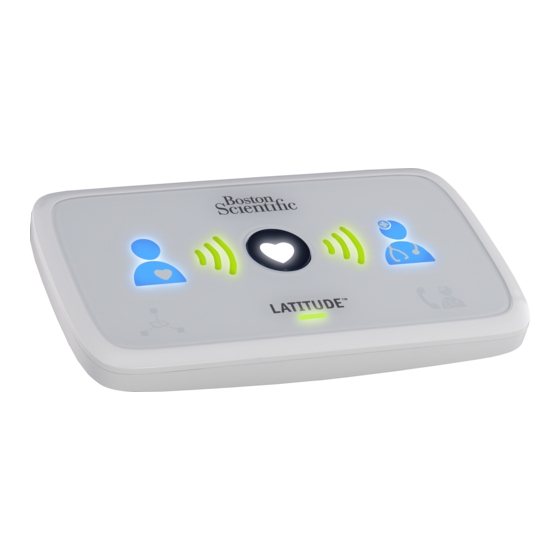
Page 18: Buttons, Connectors, And Indicators
Buttons, Connectors, and Indicators Figure 1 and Figure 2 show the buttons, indicators, and connectors on the front and back of the Communicator. Refer to “Indicator Descriptions” on page 31 for a description of each indicator. Heart button LATITUDE indicator Status button USB ports*... - Page 19 Collecting Heart Sending Patient Doctor Waves Button Waves Icon Icon Sensor LATITUDE Call Doctor Reading Icon Indicator Icon 1. Patient Icon: Stay close to the Communicator when lit any color. 2. Collecting Waves: Green = successfully collecting data. Yellow = error collecting data. 3.
-
Page 20: Installing Your Communicator
Installing Your Communicator Confirming Switch Settings • Confirm that the white switches numbered 4-8 on the bottom of the Communicator match the country switch settings as shown in Figure 3. • If the white switches on the bottom of your Communicator do not match the switch settings shown below, slide them up or down to set them as shown. -
Page 21: Connect Your Communicator To The Latitude System
Connect Your Communicator to the LATITUDE System Follow one of the three connection methods listed below to connect to the LATITUDE system: • Standard landline telephone: Follow the steps in “Using a Landline Telephone Jack Connection” on page 18. • Cellular data network: Follow the steps in “Using the LATITUDE Cellular Data Plan”... -
Page 22: Using A Landline Telephone Jack Connection
Using a Landline Telephone Jack Connection Complete the steps below to set up the Communicator for a landline telephone connection. 5. Connecting a telephone is optional. Figure 4. Using a Landline Telephone Jack Connection 1. Insert the AC adapter (included) into the jack labeled 2. - Page 23 3. Plug one end of the Communicator telephone cord (included) into the jack labeled 4. Plug the other end of the cord into the telephone jack on the wall. Note: If you have DSL Internet service, you may need to use a DSL filter between the telephone wall jack and the Communicator.
- Page 24 7. Your Communicator has successfully connected to the LATITUDE system if the wave lights are lit a solid green as shown below. Setup is complete, and no further action is needed at this time. Leave your Communicator plugged in. • If this process takes longer than several minutes, software download and installation may be occurring.
-
Page 25: Using The Latitude Cellular Data Plan
Using the LATITUDE Cellular Data Plan If you have signed up for the LATITUDE Cellular Data Plan, no telephone or Ethernet cables need to be attached. Instead, a USB Cellular Adapter provided upon subscription to the Data Plan must be connected to the Communicator. - Page 26 How to Set Up Your USB Cellular Adapter Complete the steps below to set up the Communicator for a cellular data network connection. Figure 5. Using the LATITUDE Cellular Data Plan 1. Insert the AC adapter (included) into the jack labeled 2.
- Page 27 3. Insert the USB connector of the Cellular Adapter into one of the USB ports labeled . Refer to “Figure 5. Using the LATITUDE Cellular Data Plan” on page 22. • Confirm that the USB Cellular Adapter is properly connected by verifying that the power indicator on the top of the Cellular Adapter is lit.
- Page 28 5. Your Communicator has successfully connected to the LATITUDE system if the wave lights are lit a solid green as shown below. Setup is complete, and no further action is needed at this time. Leave your Communicator plugged in. • If this process takes longer than several minutes, software download and installation may be occurring.
-
Page 29: Using A Usb Ethernet Adapter Connection
Using a USB Ethernet Adapter Connection Contact LATITUDE Patient Services at 1-866-484- 3268 to obtain a USB Ethernet Adapter. There is a cost for the adapter unless your clinic has made other arrangements. If a replacement adapter is ever needed, contact LATITUDE Patient Services. Complete the steps below to set up the Communicator for an Ethernet connection. - Page 30 Important: For the following steps, make sure you use the Ethernet cable provided with the USB Ethernet Adapter and not the telephone cord provided with the Communicator. 3. Insert the narrow end of the USB cable (included with the USB Ethernet Adapter) into one of the USB ports on the Communicator labeled 4.
-
Page 31: Software Download And Installation
8. Your Communicator has successfully connected to the LATITUDE system if the wave lights are lit a solid green as shown below. Setup is complete, and no further action is needed at this time. Leave your Communicator plugged in. • If this process takes longer than several minutes, software download and installation may be occurring. -
Page 32: Normal Operation Of The Communicator
Normal Operation of the Communicator Your Communicator performs device checks every day, and when operating normally, only the LATITUDE indicator will be lit green. Also, the Communicator automatically interrogates your implanted device on a regular schedule set by your health care provider. None of the Communicator indicators will light during a scheduled interrogation or daily device check. -
Page 33: Indicator Sequence When Using The Heart Button
Indicator Sequence When Using the Heart Button This section describes how the indicators will light after you press the Heart button. The Communicator interrogates your implanted device and then sends your data to the LATITUDE system. More details about the colors and purpose of the indicators appear later in this manual. - Page 34 All three Collecting Waves will light green. The Heart button lights solid white, showing the interrogation was a success. The Sending Waves flash green in sequence and repeat while the Communicator places a call and starts sending your data to the LATITUDE system. The Doctor icon lights blue showing the Communicator successfully sent your data to the LATITUDE system.
-
Page 35: Indicator Descriptions
Indicator Descriptions The indicators will light to indicate the Communicator’s progress when: • Manually interrogating your implanted device • Manually connecting and sending your implanted device information to the LATITUDE system • Collecting a measurement from a prescribed weight scale or blood pressure monitor One or more indicators may light or flash a different color to indicate some type of action may need to be taken. - Page 36 Collecting Waves Show the Communicator is collecting data from your implanted device. • Flash green in sequence and repeat, showing the Communicator is interrogating your implanted device. • light green for 2 minutes to indicate the interrogation was a success. Heart Button •...
- Page 37 Sending Waves Show the Communicator is connecting to the lATiTUDE system. • Flash green in sequence and repeat, showing a connection to the lATiTUDE system is in progress. • light green for 2 minutes to indicate the connection to the LATITUDE system was a success and any collected device data was sent.
- Page 38 Sensor Reading Icon Shows the Communicator has successfully communicated with a prescribed weight scale or blood pressure monitor. • Flashes green five times and lights solid green for 5 minutes to indicate the Communicator successfully received a weight or blood pressure measurement.
- Page 39 Call Doctor Icon Lights yellow or red (flashing or solid) to signal a problem that you should report to your health care provider. Refer to the error in “Troubleshooting Errors” on page 38. A red light ranks higher than a yellow light.
-
Page 40: Status Button
Status Button The status button is located on the back of the Communicator as shown in Figure 7. Figure 7. Status Button The Status button performs one the following actions depending on how long the button is pressed: • Press for less than 3 seconds: The Communicator indicators will light to show: •... -
Page 41: Confirming Successful Operation
Confirming Successful Operation You can use the status button to check if the Communicator has been operating normally. The above image shows that all the Collecting and Sending Waves are lit green, confirming that the last interrogation and the last connection to the lATiTUDE system were a success. -
Page 42: Troubleshooting Errors
Troubleshooting Errors Troubleshooting Icon and LATITUDE Indicator Errors One or more of the indicators on the front of the Communicator may light or flash to indicate some type of Communicator, communication, or LATITUDE system error. A general description of the types of errors are shown in Figure 8. - Page 43 Heart Button is Flashing LATITUDE Indicator is Green You need to complete a previously Description: scheduled interrogation. Action: • Press the Heart button to complete the interrogation. • if the heart button is lit a solid white, the interrogation has been a success.
- Page 44 No Indicators are Lit Description: No indicators are lit. The Communicator is not connected to electric power or it is not functioning. Action: • if the lATiTUDE indicator is not lit, check that both ends of the AC adapter are plugged in firmly. •...
- Page 45 LATITUDE Indicator is Flashing Yellow No Other Indicators are Lit Description: The LATITUDE indicator is flashing yellow. The Communicator is starting up or may be downloading and installing software. This process typically lasts only one minute but may take up to 10 minutes. Action: •...
- Page 46 Call Doctor Icon is Red LATITUDE Indicator is Yellow Description: The Call Doctor icon is red (flashing or solid), and the LATITUDE indicator is yellow. A potential problem with your implanted device was detected, but the Communicator cannot send any information collected from your implanted device to the LATITUDE system.
- Page 47 Call Doctor Icon is Yellow LATITUDE Indicator is Yellow Description: The Call Doctor icon is yellow (flashing or solid), and the LATITUDE indicator is yellow. Indicates one of the following errors: • Your Communicator is currently unable to monitor your implanted device.
- Page 48 Call Doctor Icon is Yellow LATITUDE Indicator Not Lit Description: The Call Doctor icon is lit a solid yellow, and the LATITUDE indicator is not lit. This indicates your Communicator may not be working properly. Action: You may need a replacement Communicator.
-
Page 49: Troubleshooting Yellow Wave Indicator Errors
Troubleshooting Yellow Wave Indicator Errors One or more of the Wave indicators will light yellow to indicate some type of error as described in the following Wave sections. Wave indicators light yellow for 60 minutes unless the error is resolved sooner. After 60 minutes, all Wave lights are turned off and the LATITUDE indicator is lit green, even if the problem was not resolved. - Page 50 One Yellow Collecting Wave Description: The Communicator was unable to start an interrogation of your implanted device, or your implanted device was out of range at the time of the attempted interrogation. Action: • Ensure the Communicator is optimally placed as described in “Where to Place Your Communicator”...
- Page 51 Two Yellow Collecting Waves Description: The Communicator started but was not able to complete the interrogation within the time allowed. Action: • Ensure the Communicator is optimally placed as described in “Where to Place Your Communicator” on page 12. • Face the Communicator. Sit directly in front of the Communicator.
- Page 52 Three Yellow Collecting Waves Description: Any of the following reasons could cause this error: • You may have exceeded your weekly interrogation limit, or you may not be allowed to use the Heart button. • The Communicator was unable to establish wireless communication with your implanted device due to interference from another person’s...
- Page 53 One Yellow Sending Wave Description: The Communicator was not able to make a connection to the lATiTUDE system for one of the following reasons: • No dial tone was detected when attempting to use the telephone line. • No cellular providers were detected when attempting to connect using the lATiTUDE Cellular Data Plan.
- Page 54 • If you have DSL Internet service, ensure you are using a DSL filter between the Communicator and the telephone wall jack. • Check that the analog telephone service supports the tone dialing mode. if using the lATiTUDE Cellular Data Plan: •...
- Page 55 If using the USB Ethernet Adapter: • Make sure the USB cable provided with the USB Ethernet Adapter is connected at one end to the UsB Ethernet Adapter and at the other end to the Communicator. • Make sure the Ethernet cable provided with the USB Ethernet Adapter is firmly connected at one end to the USB Ethernet Adapter...
- Page 56 Two Yellow Sending Waves Description: An attempt to connect to the lATiTUDE system failed due to connection issues relating to the landline telephone, cellular network, or Ethernet. If using a landline telephone connection, another device (telephone, answering machine, or computer) may be using or attempting to use the telephone line.
- Page 57 • Check that the switches on the bottom of the Communicator are set correctly for your country and whether you need to dial a number to get an outside line. Refer to “Confirming Switch Settings” on page 16. if using the lATiTUDE Cellular Data Plan: •...
- Page 58 Three Yellow Sending Waves Description: The Communicator was able to establish a connection, but no information reached the lATiTUDE system. • Check that the switches on the Action: bottom of the Communicator are set correctly for your country and whether you need to dial a number to get an outside line.
-
Page 59: Latitude Cellular Data Plan
LATITUDE Cellular Data Plan The lATiTUDE Cellular Data Plan uses a cellular data network rather than a standard landline telephone connection to send your implanted device data to the LATITUDE system. The LATITUDE Cellular Data Plan is an optional subscription service that must be activated before your Communicator can use this service. -
Page 60: Activating The Latitude Cellular Data Plan
Activating the LATITUDE Cellular Data Plan Contact LATITUDE Patient Services at 1-866-484- 3268 to subscribe to the LATITUDE Cellular Data Plan. There is a cost for this service unless your clinic has made other arrangements. An activated plan works only with your LATITUDE NXT USB Cellular Adapter. -
Page 61: Discontinuing Your Latitude Cellular Data Plan
Discontinuing Your LATITUDE Cellular Data Plan Contact LATITUDE Patient Services at 1-866-484- 3268 to discontinue use of the LATITUDE Cellular Data Plan. You will need to discontinue your subscription if you stop using the LATITUDE system or if you want to return to using a landline telephone connection. - Page 62 button, the Communicator checks to make sure that the interrogation is permitted. You should only use the Heart button if it is flashing or when instructed to do so by your health care provider. If you press the Heart button by mistake (not intending to perform an interrogation), press and hold the Heart button again for at least 5 seconds to cancel the interrogation.
-
Page 63: Interrupted Electrical Power
Interrupted Electrical Power The Communicator has internal memory that stores your interrogation and other information in case the electrical power is interrupted or the AC adapter is unplugged. The LATITUDE indicator will transition back to green once power is restored to the Communicator. -
Page 64: Traveling With Your Communicator
3. Watch the front of the Communicator. The Sending Waves should flash green in sequence and repeat, showing a connection to the LATITUDE system is in progress. 4. Wait several minutes for the connection to complete. 5. If the connection was successful, all three of the Sending Waves will light green for 2 minutes. -
Page 65: Communicator Use Of The Telephone System (Landline Telephone Only)
Note (Model 6280 only): Your Communicator is designed to be used only in the United states, Canada, Puerto Rico, and Mexico. Use of the Communicator in other countries may be restricted due to radio-frequency (RF) laws. Please contact LATITUDE Patient Services at 1-866-484-3268 for specific information. -
Page 66: Using The Telephone While The Communicator Is Making A Call
If you have other telephone equipment (including fax machine, answering system or computer modem) connected to the same phone line and the line is in use, the Communicator will wait and attempt to place a call later. If you have heavy phone line usage that delays or prevents the Communicator from placing or completing phone calls, it may be appropriate to install an additional telephone line. -
Page 67: Dsl Internet Service
DSL Internet Service This section applies only if you are using a landline telephone jack connection to the LATITUDE system. If you have digital subscriber line (DSL) Internet service provided through your telephone line, you may need to install a DSL filter between the wall phone jack and the LATITUDE Communicator. -
Page 68: Cleaning The Communicator And Accessories
CAUTIONS: • Do not drop or mishandle the Communicator or its accessories in a manner that would cause damage. • Avoid getting liquid on the unit other than cleaning it as recommended. Do not use abrasive cloth or solvents to clean the unit. •... -
Page 69: Returning, Replacing, Or Disposing Of The Communicator, Usb Cellular Adapter
CAUTIONS: • Do not use other cleaning fluids. They may damage the front lens of the Communicator. Never spray any cleaning fluid directly on the Communicator front lens. Do not allow moisture to accumulate on or around the lens or heart button. -
Page 70: Setting Switches For Pbx Or Dial-Out Numbers
Setting Switches for PBX or Dial-out Numbers (This section applies only to landline telephone connections.) You can use your Communicator with a private branch exchange (PBX) in a managed care facility, hotel, or other location that requires you to enter a dial-out number or prefix to place an outside call. -
Page 71: Connecting The Usb Sensor Adapter
Connecting the USB Sensor Adapter The USB sensor adapter is included with a LATITUDE weight scale and blood pressure monitor. The USB sensor adapter provides a wireless connection between these products and the Communicator. Refer to Figure 10. Figure 10. USB Sensor Adapter Connection 1. -
Page 72: Specifications
Specifications Models: 6280 and 6290 (Unless specified, values apply to both models.) Dimensions: Length: 8.00 in (20.3 cm) Width: 4.50 in (11.4 cm) Height: 2.71 in (6.9 cm) Weight: 0.83 lbs ( 0.38 kg) Power Source: 5.0 VDC, 3.0 A, continuous service Class II AC adapter, globTek Model gTM41061-... - Page 73 Storage and Transport Up to 93% noncondensing humidity*: Operating Pressure: 70 to 106 kPa Storage and Transport 50 to 106 kPa Pressure*: Protection Against ingress of solid IP21 (≥12.5 mm diameter) Foreign Objects: Protection Against ingress of Water: IP21 (light rain proof) Communicator Implanted Device Radio (Model 6280): Receive Bandwidth: +190/-160 kHz...
- Page 74 USB Sensor Adapter: 2.4 GHz wireless USB dongle Delta Mobile systems Model DM210 ® Boston Scientific Model 6454 (included with LATITUDE weight scale and blood pressure monitor) Operational Frequency: 2400.0 to 2480.0 MHz Modulation Type: Adaptive Frequency Hopping Effective Radiated...
- Page 75 LATITUDE NXT USB Cellular Adapter (Model 6295): TX 824-849 MHz gsM-850: RX 869-894 MHz Effective Radiated Power: 22.93 dBm PCs-1900: TX 1850-1910 MHz RX 1930-1990 MHz Effective Radiated Power: 26.42 dBm W-CDMA 850: TX 824-849 MHz RX 869-894 MHz Effective Radiated Power: 15.83 dBm W-CDMA 1900: TX 1850-1910 MHz...
-
Page 76: Safety And Standards Compliance
Safety and Standards Compliance • Changes or modifications not expressly approved by Boston Scientific could void the user’s authority to operate this equipment. • Before each use, visually inspect your Communicator to make sure the housing has no cracks and the AC adapter and any other connecting items are intact. - Page 77 • Do not use the Communicator in the presence of flammable gas mixtures, including anesthetics, oxygen, or nitrous oxide. • The user is cautioned to maintain an 8 in. (20 cm) spacing from the product to ensure compliance with Federal Communications Commission/Industry Canada (FCC/IC) requirements.
- Page 78 • This equipment complies with Part 68 of the FCC rules and the requirements adopted by the Administrative Council for Terminal Attachments (ACTA). On the bottom of this equipment is a label that contains, among other information, a product identifier in the format US: AAAEQ##TXXX.
- Page 79 Meteorological Aids (i.e., transmitters and receivers used to communicate weather data), the Meteorological Satellite, or the Earth Exploration Satellite Services and must accept interference that may be caused by such stations, including interference that may cause undesired operation. This transmitter shall be used only in accordance with the FCC Rules governing the Medical Device Radiocommunication Service.
- Page 80 • if the Communicator causes harm to the telephone network, the telephone company will notify you in advance that temporary discontinuance of service may be required. But if advance notice isn’t practical, the telephone company will notify the customer as soon as possible.
-
Page 81: Essential Performance
Essential Performance The performance of the Communicator that is determined to be essential by Boston Scientific for electromagnetic compatibility (EMC) testing, as per iEC 60601-1-2, is the ability to: • Communicate with your implanted device. • Identify alert conditions in your implanted device. -
Page 82: Electromagnetic Emissions And Immunity
Electromagnetic Emissions and Immunity Table 1. Guidance and manufacturer’s declaration— electromagnetic emissions—for all equipment and systems Emissions test Compliance Electromagnetic environment—guidance RF emissions Group 1 The lATiTUDE Communicator (CISPR 11) uses RF energy only for its internal function. Therefore, its RF emissions are very low and are not likely to cause any interference in nearby electronic equipment. - Page 83 Table 2. Guidance and manufacturer’s declaration— electromagnetic immunity—for all equipment and systems IEC 60601 test Electromagnetic Immunity test Compliance level level environment—guidance Electrostatic ±6 kV contact ±8 kV contact The relative discharge humidity should be (ESD) (IEC ±8 kV air ±15 kV air at least 15 percent.
- Page 84 IEC 60601 test Electromagnetic Immunity test Compliance level level environment—guidance Voltage <5% U <5% U Mains power quality dips, short (>95% dip (>95% dip should be that of a interruptions, in U ) for 0.5 in U ) for 0.5 typical commercial and voltage cycle...
- Page 85 Table 3. Guidance and manufacturer’s declaration— electromagnetic immunity—for equipment and systems that are not life supporting a b c d IEC 60601 Compliance Electromagnetic environment— Immunity test test level level guidance Portable and mobile RF communications equipment should be used no closer to any part of the lATiTUDE Communicator, including cables, than the...
- Page 86 IEC 60601 Compliance Electromagnetic environment— Immunity test test level level guidance Radiated 3 V/m 10 V/m d = 0.5 √P (80 MHz to 1000 RF (iEC 80 Mhz to 80 Mhz to MHz) 61000-4-3) 2.5 GHz 1000 Mhz d = 0.29 √P (380 MHz to 390 MHz) 3 V/m d = 0.36 √P (430 MHz to 470 1 ghz to MHz) 2.7 GHz d = 0.21 √P (800 MHz to 960 MHz)
- Page 87 These guidelines may not apply in all situations. Electromagnetic propagation is affected by absorption and reflection from structures, objects, and people. The separation distances are calculated using the following equation adopted from the 4th edition draft of IEC 60601-1-2: d = (5/E) √P where P is the maximum output power of the transmitter in watts (W) according to the transmitter manufacturer, d is the separation distance in meters (m), and E is the compliance level.
- Page 88 LATITUDE Communicator Patient Manual ®...
-
Page 89: Software
Software The software included in this product contains copyrighted software that is licensed under the GNU General Public License (GPL). Under the terms of the GPL as published by the Free Software Foundation, you may obtain the complete corresponding source code from us for a period of three years after our shipment of this product. -
Page 90: Explanation Of Product And Label Symbols
Explanation of Product and Label Symbols Symbol Meaning Input from telephone jack Output to telephone (optional) AC/DC adapter power input Direct current (DC) Universal serial bus (USB) connector Part number serial number Reference number non-ionizing electromagnetic radiation IEC 60601 Class II medical equipment, protection against electrical shock Manufacturer Date of manufacture... - Page 91 Symbol Meaning Ready for LATITUDE NXT 3.0 CE mark of conformity (applies to USB sensor adapter) Indicates the product complies with applicable Australia radiocommunications standards (applies to USB sensor adapter) Authorized representative in the European Community (applies to distribution box) Australian sponsor address (applies to distribution box) Power indicator (applies to USB Cellular Adapter)
-
Page 92: Frequently Asked Questions
Frequently Asked Questions These FAQs are designed to point you to the right section in this manual for the answers. Does the Communicator call 911 in an emergency? No. The LATITUDE system is not meant to assist with health emergencies. If you are not feeling well, call your health care provider or dial 911. -
Page 93: How Do I Know The Communicator Is Working
How do I know the Communicator is working? See “Normal Operation of the Communicator” on page 28. What do these lights mean? See “Indicator Descriptions” on page 31 or “Troubleshooting Errors” on page 38. How do I manually send my data? See “Indicator Sequence When Using the Heart Button”... - Page 94 LATITUDE Communicator Patient Manual ®...
Need help?
Do you have a question about the LATITUDE 6280 and is the answer not in the manual?
Questions and answers