Table of Contents
Advertisement
Advertisement
Table of Contents

Related Manuals for Topcon IP-S3 HD1


Summary of Contents for Topcon IP-S3 HD1
- Page 1 SURVEYING INSTRUMENTS INSTALLATION MANUAL Mobile Mapping System IP-S3 HD1 For more information contact Synergy Positioning Systems or visit the Synergy Positioning Systems website at www.synergypositioning.co.nz All branches: Phone 0800 867 266 Email: info@synergypositioning.co.nz 72008 92080...
- Page 2 • Some of the diagrams shown in this manual may be simplified for easier understanding. • This manual is protected by copyright and all rights are reserved by TOPCON CORPORATION. • Except as permitted by Copyright law, this manual may not be copied, and no part of this manual may be reproduced in any form or by any means.
-
Page 3: Table Of Contents
CONTENTS PRECAUTIONS FOR SAFE OPERATION..........1 PRECAUTIONS ..................3 LASER SAFETY INFORMATION .............. 6 SYSTEM CONFIGURATION ..............7 4.1 Standard Package Components ............7 IP-S3 Cube ....................7 4.2 Optional Accessories ................. 7 Mount kit ....................7 Wheel encoder ..................7 ... - Page 4 9.3 Indicator Box ..................30 Status LED .....................30 GNSS LED .....................30 LED display ....................31 Resetting the timing box .................31 Clearing NVRAM (Initializing GNSS) ............31 9.4 Removing of IP-S3 Cube ..............32 10. SPECIFICATIONS ................... 33 11.
-
Page 5: Precautions For Safe Operation
1. PRECAUTIONS FOR SAFE OPERATION For the safe use of the product and prevention of injury to operators and other persons as well as prevention of property damage, items which should be observed are indicated by an exclamation point within a triangle used with WARNING and CAUTION statements in this operator’s manual. The definitions of the indications are listed below. - Page 6 1. PRECAUTIONS FOR SAFE OPERATION Do not place the instrument in a damaged case. The instrument could be dropped and cause injury. Carefully carry this instrument. Dropping it will cause injury of persons or trouble/wrong operation of the instrument. Power Supply ...
-
Page 7: Precautions
2. PRECAUTIONS Shock to the instrument When carrying or transporting this instrument, put it into the special shipping case (Optional). If the instrument is exposed to extreme shock, it may malfunction or be operated wrongly. Dew condensation After operating the instrument in a place with much rain/moisture, dry the instrument completely and then store it into the case. - Page 8 2. PRECAUTIONS Mounting the wheel encoder To mount the wheel encoder, install the overfender according to the vehicle laws in your area, and obtain the automobile inspection certificate again. Privacy The data collected with this device can include images that violate privacy laws. Delete or alter images that violate privacy rights before making the data publicly available.
- Page 9 2. PRECAUTIONS Exporting this product (Relating EAR) • This product is equipped with the parts/units, and contains software/technology, which are subject to the EAR (Export Administration Regulations). Depending on countries you wish to export or bring the product to, a US export license may be required. In such a case, it is your responsibility to obtain the license.
-
Page 10: Laser Safety Information
3. LASER SAFETY INFORMATION The instrument is classified as the following class of Laser Product according to IEC Standard Publication 60825-1 Ed.2.0: 2007 and United States Government Code of Federal Regulation FDA CDRH 21CFR Part 1040.10 and 1040.11 (Complies with FDA performance standards for laser products except for deviations pursuant to Laser Notice No.50, dated June 24, 2007.) Class 1 Laser Product Laser beam is emitted... -
Page 11: System Configuration
4. SYSTEM CONFIGURATION Standard Package Components IP-S3 Cube Refer to "STANDARD PACKAGE COMPONENTS" (enclosed paper). IP-S3 cube has already been assembled. Because it has already been adjusted, do not disassemble Optional Accessories Mount kit Slide bar (with clamp lever) : 1 set Carrier plate : 2 pcs. -
Page 12: Car
4. SYSTEM CONFIGURATION Vehicle Preparation Car Wheel encoder types are determined by the car model. Contact your local dealer. To prevent the car from being reflected within the scan range of scanner, select a car model where you can mount the instrument at the rear. -
Page 13: Installing And Arranging Cables
5. INSTALLING AND ARRANGING CABLES The outline for installing the devices is shown below. The cables from the IP-S3 cube are connected to the devices from the inside of the vehicle through the windows. Roof carrier Cable IP-S3 cube Mount kit Relay connector Gasket Timing box... -
Page 14: Ip-S3 Cube Diagram
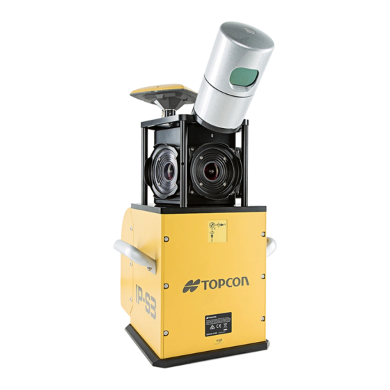
6. IP-S3 CUBE DIAGRAM The IP-S3 cube has already been assembled. Because it has already been adjusted, do not disassemble it. Scanner GNSS antenna Spherical camera Handle USB 3.0 cable (long) Camera cable (in the case) Scanner cable GNSS cable IMU cable... -
Page 15: Operation Flow Of Ip-S3 System
• Installing the wheel encoder • Installing the gasket IP-S3 HD1 Installation Manual (this manual) Install the IP-S3 cube when surveying (parts that are removed from the car) • Installing the IP-S3 cube to the mount kit • Connecting the cables •... -
Page 16: Prepare The Vehicle
8. PREPARE THE VEHICLE When preparing the vehicle, install the following devices. Install the Roof Carrier 1. Mount the roof carrier onto the car. For details, refer to the roof carrier's instruction manual. Roof carrier Install the Mount Kit Mount the carrier plate onto the roof carrier bar using the following procedure. (The carrier plate has the binding band to clamp the cables.) 1. - Page 17 8. PREPARE THE VEHICLE 5. Mount the side base to the carrier plate using carrier base B and the 8 hexagonal head cap screws. The side base must be pointed in the direction shown below. When the instrument is shipped, the slide bases are secured to the slide bar with 4 clamp levers. Detach the clamp levers from the slide bar before using the slide bases.
- Page 18 8. PREPARE THE VEHICLE 6. Remove the 4 clamp levers, spring washers, and plain washers from the side bar. 7. Put the slide bar on the slide base. 8. As shown in the illustration below, locate where the sidebar is fully extended and securely tighten the clamp lever and step screw.
- Page 19 8. PREPARE THE VEHICLE 11. Loosen the 4 clamp levers, retract the slide bar, and place it in the the center of the roof carrier. Clamp lever Slide bar Retract. 12. Securely tighten the 4 clamp levers by hand. The knob parts of all clamp levers used for this product can be rotated by pulling them in the direction indicated by the arrow in the diagram below.
-
Page 20: Install The Wheel Encoder
8. PREPARE THE VEHICLE Install the Wheel Encoder Required Parts The number in parentheses is quantity. Wheel encoder (1) Wheel encoder cable (1) Wheel encoder nut and bolt (Size and quantity are different between car models.) Installing the wheel encoder 1. -
Page 21: Installing The Wheel Encoder Cable
8. PREPARE THE VEHICLE 3. Make a hole on the overfender of the rear tire to fix the wheel encoder bar. Hole Overfender Wheel encoder bar 4. Pass the wheel encoder bar through the hole on the overfender of the rear tire. 5. -
Page 22: Install The Gasket
8. PREPARE THE VEHICLE • Arrange the wheel encoder cable so that it stays within the vehicle width. • The quantity of wheel encoder parts is different from vehicle to vehicle. Contact your local dealer for more information. Install the Gasket After mounting the IP-S3 cube on the roof of the vehicle, connect it to the timing box using the included cables. -
Page 23: Installing The Ip-S3 Cube
9. INSTALLING THE IP-S3 CUBE Install the IP-S3 Cube To prevent theft, only install the IP-S3 cube to the mount kit when surveying. The IP-S3 cube has already been calibrated. Do not disassemble it. Warning Carefully attach the IP-S3 cube to the mount kit. Damage to the instrument or serious ... - Page 24 9. INSTALLING THE IP-S3 CUBE 4. Make sure that the four quick shoe lock pins are lowered. 5. Loosen the 2 clamp levers of the quick shoe. Quick shoe Clamp lever Lock pin Lock pin 6. Hold both handles of the IP-S3 cube, and place it on the quick shoe as shown in the image below.
- Page 25 9. INSTALLING THE IP-S3 CUBE 7. Place the IP-S3 cube against the fixing pins of the quick shoe. Then, raise the lock pins to make sure that the IP-S3 cube is secured. Fixing pin Lock pin Lock pin 8. Tighten the two clamp levers. Handle Clamp lever Washer assembled hexagonal...
- Page 26 9. INSTALLING THE IP-S3 CUBE 10. Loosen the clamp lever of the slide bar, and retract the slide bar as shown in the image below. 11. Tighten the clamp lever of slide bar. • When surveying, extend and use the slide bar. •...
-
Page 27: Connect The Cables
9. INSTALLING THE IP-S3 CUBE Connect the Cables Warning To avoid electric shock, turn off the car engine before connecting the power cables. After mounting the IP-S3 cube on the roof of the vehicle, connect it to the timing box using the included cables. -
Page 28: Connecting The Power Cable (Battery Side)
1. Connect the power cable to the car battery. The wire on the battery side of the power cable is exposed. Topcon recommends placing the exposed wire inside a connector. For safety and ease of use, connect the red cable to the positive (+) terminal, and the black cable to the negative (-) terminal. -
Page 29: Preparing A Personal Computer
9. INSTALLING THE IP-S3 CUBE • Power is supplied to IP-S3 from the car battery directly. Even if the car engine is turned off, IP-S3 operates and the car battery discharges power. Whenever the car engine stops, turn off the timing box switch. -
Page 30: Connect The Timing Box Ethernet Cable
9. INSTALLING THE IP-S3 CUBE Connect the Timing Box Ethernet Cable 1. Remove the cap from the timing box Ethernet cable. 2. Connect the IP-S3 side of the Ethernet cable to the Ethernet port of the IP-S3 cube. Ethernet cable [Timing Box Side] is written on the tag of this part. -
Page 31: Connect The Indicator Box Cable
9. INSTALLING THE IP-S3 CUBE Connect the Indicator Box Cable 1. Remove the cap from the indicator box port. 2. Using the indicator box cable, connect the timing box to the indicator box as shown below. Indicator box cable [Indicator Side] is [Timing Box Side] is written written on the tag of... -
Page 32: Connect The Ip-S3 Cube Cables
9. INSTALLING THE IP-S3 CUBE Connect the IP-S3 Cube Cables 1. Connect all cables from the timing box to the IP-S3 cube, and ty-wrap them for easy storage. Cube side Timing Box side IMU (Tag: brown) [1]IMU (Tag: brown) Camera (Tag: purple) [2]Camera (Tag: purple) -
Page 33: Fixing The Cables
9. INSTALLING THE IP-S3 CUBE Fixing the Cables • After connecting all cables, attach them to the binding band of the carrier plate. • Fix the cables without excessive tension. Carrier plate Binding band Connector (Detachable) -
Page 34: Indicator Box
9. INSTALLING THE IP-S3 CUBE Indicator Box Using the LEDs of the IP-S3 indicator box, check if the IP-S3 system operates properly. Status LED LAN LED Switch LED GNSS LED System reset button NVRAM Clear button Indicator box Status LED After turning the power on, if the Status LED blinks red some part of the IP-S3 system is not operating correctly. -
Page 35: Led Display
9. INSTALLING THE IP-S3 CUBE LED display LED status is described in the table below. For all errors, except GNSS initialization, follow the steps in "Resetting the Timing Box" below. For descriptions of errors, see the Mobile Master Field Instruction Manual. Indication Contents Solid red... -
Page 36: Removing Of Ip-S3 Cube
9. INSTALLING THE IP-S3 CUBE Removing of IP-S3 Cube After surveying, follow the steps below to remove the IP-S3 cube. 1. Disconnect the cables. 2. Loosen the clamp lever of slide bar and extend the slide bar. 3. Loosen the clamp lever of the quick shoe. 4. -
Page 37: Specifications
10.SPECIFICATIONS IP-S3 Timing box Dimensions 260 (W) × 160 (D) × 121 (H) mm Weight 3.0kg(6.6lb) Operating temperature range -20°C to 50°C (-4° to 122°F) Storage temperature range -30°C to 60°C (-22° to 140°F) Dustproof/Waterproof IP65 (JIS C0920:2003) Input/Output port Power supply, Ethernet, scanner, spherical camera, wheel encoder, IMU, GNSS antenna Time resolution... - Page 38 10. SPECIFICATIONS Acceleration bias stability 7.5 mg Operating temperature range -40°C to 65°C (-40° to 149°F) Storage temperature range -50°C to 80°C (-58° to 176°F) Dustproof/Waterproof IP67 (JIS C0920:2003) Vibration 6Grms(20Hz to 2000Hz) Shock 7G(6 to 10msec 1/2Sine) Laser scanner Point density 700000 points/sec Valid range...
-
Page 39: Regulations
11.REGULATIONS Region/ Directives/ Labels/Declarations Country Regulations U.S.A. FCC-Class A FCC Compliance WARNING: Changes or modifications to this unit not expressly approved by the party responsible for compliance could void the user's authority to operate the equipment. NOTE: This equipment has been tested and found to comply with the limits for a Class A digital device pursuant to Part 15 of the FCC Rules. - Page 40 This is a CLASS A product. In a domestic environment this product may cause radio interference in which case the user may be required to take adequate measures. Model: Mobile Mapping System IP-S3 HD1 Manufacturer Name: TOPCON CORPORATION Address:...
- Page 41 Please see the attached address list or the following website for contact addresses. GLOBAL GATEWAY http://global.topcon.com/ © 2015 TOPCON CORPORATION ALL RIGHTS RESERVED...
Need help?
Do you have a question about the IP-S3 HD1 and is the answer not in the manual?
Questions and answers