Advertisement
Quick Links
Malm Fireplaces, Inc.
368 Yolanda Avenue - Santa Rosa, Ca 95404
(707) 523-7755 - Fax: (707) 571-8036
info@malmfireplaces.com
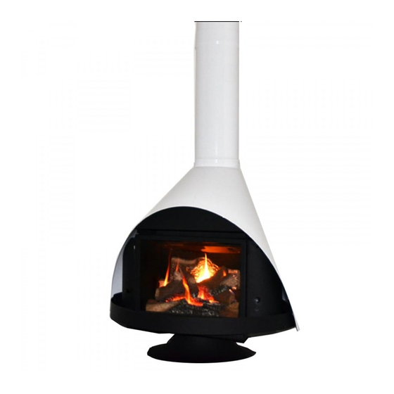
34 Zircon
Direct Vent
Listed: VENTED GAS FIREPLACE HEATER
CANADA and U.S.A. - Certified to: CAN/CGA-2.17-M91(R2009)
Tested to:ANSI Z21.88-2017 & CSA 2.33-2017
Assembly And Installation Instructions
LEAVE THESE INSTRUCTIONS WITH THE OWNER.
Their are two parts to these instructions. The Malm unit instructions and the Regency L234
insert instructions. The operating and maintenace instructions for the Regency unit are in-
cluded as part of thes Malm 34ZDV instructions.
Warning:
FIRE OR EXPLOSION HAZARD
Failure to follow safety warnings exactly could result in serious injury, death, or property
damage.
Do not store or use gasoline or other flammable vapors and liquids in the vicinity of
this or any other appliance.
WHAT TO DO IF YOU SMELL GAS
Do not try to light any appliance.
Do not touch any electrical switch; do not use any phone in your building.
Leave the building immediately.
Immediately call your gas supplier from a neighbor's phone. Follow the gas
supplier's instructions.
If you cannot reach your gas supplier; call the fire department.
Installation and service must be performed by a qualified installer, service agency or the
gas supplier.
WARNING: Improper installation, adjustment, alteration, service or maintenance can cause
injury or property damage. Refer to this manual.
Do not use this appliance if any part has been under water. Immediately call a qualified
service technician to inspect the heater and replace any part of the control system and
any gas control that has been under water.
This appliance is not for use with glass doors.
Tested & Listed by LabTest
Certified for use in USA &
Canada. Certifi é pour une utilisation
aux Etats-Unis et Canada
Shown with optional matching base.
Page - 1
34ZDV 6/1/18
Advertisement

Subscribe to Our Youtube Channel
Related Manuals for Malm Fireplaces 34 Zircon Direct Vent


Summary of Contents for Malm Fireplaces 34 Zircon Direct Vent
-
Page 1: Assembly And Installation Instructions
Malm Fireplaces, Inc. 368 Yolanda Avenue - Santa Rosa, Ca 95404 (707) 523-7755 - Fax: (707) 571-8036 info@malmfireplaces.com 34 Zircon Direct Vent Tested & Listed by LabTest Certified for use in USA & Canada. Certifi é pour une utilisation aux Etats-Unis et Canada Listed: VENTED GAS FIREPLACE HEATER CANADA and U.S.A. -
Page 2: General Information
This appliance has been tested in accordance with National Safety Standards and has been certified by Lab Test for installation and operation as described in this manual. Contact Malm Fireplaces for questions regarding installation or operation of this unit. -
Page 3: Corner Installation
CLEARANCES Make sure that minimum clearances to combustible materials are maintained during installation in- cluding adequate space for the proper operation and servicing of the heater. The minimum clearances from the appliance to combustibles are shown on figures 1 and 2. Place the appliance on a flat, solid, continuous surface (i.e. - Page 4 BACK OF UNIT GAS LINE ATTACHMENT The gas supply line must be installed at the rear center of the gas unit. This supply line must be a minimum of 1/2", black iron type pipe. A separate manual shut off GAS SHUT valve should always be used.
-
Page 5: Vertical Installation
VENTING THE APPLIANCE MUST NOT BE CONNECTED TO A CHIMNEY FLUE SERVING A SEPARATE SOLID FUEL BURNING APPLIANCE. This appliance is designed to be attached to two 3" (76mm) co-linear aluminium flex running the full length of the chimney connector from the unit to the support box. The flue length must be a minimum length of 8' (2.44m) and a maximum of 35' (10.7m). - Page 6 joists, roof rafters, framing or other materials will obstruct the venting system. You may wish to re- locate the appliance, or to offset, to avoid cutting load-bearing members. There is a 1-7/8" offset from the center of the support box to the center of the DirectVent Pro 4"...
- Page 7 Step 7. Slip the Roof Flashing over the Pipe Section(s) protruding through the roof. Use a non- hardening sealant between the Roof Flashing and the roofing to prevent water leakage. Secure the base of the Roof Flashing to the roof with roofing nails.
- Page 8 Center of Direct- 1-7/8" Vent Pro Center of Suport Box Figure 15 There is a 1-7/8" offset from the center of the support box to the center of the DirectVent Pro 4" x 6 5/8" center. The Support Box can be installed with this offset oriented in any direction. Figure 17 Step 10 - Note 3 continued For a chase enclosure, it may be con-...
-
Page 9: Cathedral Ceiling Installation
CATHEDRAL CEILING TABLE 3 INSTALLATION ROOF PITCH MINIMUM HEIGHT Step 1. Follow installation Steps 1 and 2 under Feet Meters Vertical Terminations. Step 2. Flat to 7/12 Using the plumb bob, mark Figure 18 the center line of the venting system on the ceil- Over 7/12 to 8/12 0.46 ing and drill a small hole through the ceiling and... - Page 10 DuraVent DirectVent Pro GENERAL MAINTENANCE Conduct an inspection of the venting system annually. Recommended areas to inspect are as follows: 1. Check areas of the Venting System which are exposed to the elements for corrosion. These will ap- pear as rust spots or streaks, and in extreme cases, holes. These component should immediately be replaced.
- Page 11 Unit Connector to Support Box Connection 3 inch flex is used from the unit connectors to the support box. It is mandatory that the ends be con- nected to the correct connections on the support box. The exhaust from the unit must be connected to the corresponding exhaust connector on the support box.
- Page 12 34” Zircon Direct Vent Through the Wall Vent Installation The 34 Zircon Direct Vent can be installed with a through the wall kit available from Malm. The through the wall vent kit consists of the following: 1 - Inner and Outer support box.
- Page 13 If the location has a stud blocking the installation it must be cross framed prior to installation of the support box. The support box requires a 13 1/4 x 13 1/4 framing. The support box must be installed with the Exhaust connector at the bottom of the box. Nailing flanges are included that can be attached to the support box if needed.
- Page 14 46DVA-HSCH DURA VENT WITH 46DVA-GK OUTER DIRECTVENT PRO INSTALLED High-Wind Sconce SIDE VIEW Termination Cap FRONT VIEW OF WALL SUPPORT COMPLETE ASSEMBLY BACK VIEW OF WALL SUPPORT DuraVent DirectVent Pro GENERAL MAINTENANCE Conduct an inspection of the venting system annually. Recommended areas to inspect are as follows: 1.
- Page 15 Regency unit for your installation. The vent restrictor must be checked and the burner air shutter for your installation. A copy of these instructions are available online at www.malmfireplaces.com Malm Fireplaces, Inc. 368 Yolanda Avenue Santa Rosa, Ca 95404 (707) 523-7755 - (800) 535-8955 Fax: (707) 571-8036 email: info@malmfireplaces.com...
Need help?
Do you have a question about the 34 Zircon Direct Vent and is the answer not in the manual?
Questions and answers