Table of Contents
Advertisement
Quick Links
P.O. BOX 265
OGDENSBURG, NY
U.S.A. 13669-0265
A V T E C H
TEL: 888-670-8729 (USA & Canada) or +1-613-686-6675 (Intl)
FAX: 800-561-1970 (USA & Canada) or +1-613-686-6679 (Intl)
info@avtechpulse.com
INSTRUCTIONS
MODEL AVR-AHF-1-B
250 Volts, 100 kHz
PULSE GENERATOR WITH
IEEE 488.2 AND RS-232 CONTROL
SERIAL NUMBER: ____________
E L E C T R O S Y S T E M S
N A N O S E C O N D
W A V E F O R M
S I N C E
-
http://www.avtechpulse.com/
E L E C T R O N I C S
1 9 7 5
BOX 5120, LCD MERIVALE
X
OTTAWA, ONTARIO
CANADA
L T D .
K2C 3H5
Advertisement
Table of Contents

Related Manuals for Avtech AVR-AHF-1-B series


Summary of Contents for Avtech AVR-AHF-1-B series
- Page 1 A V T E C H E L E C T R O S Y S T E M S L T D . N A N O S E C O N D W A V E F O R M E L E C T R O N I C S S I N C E 1 9 7 5...
-
Page 2: Warranty
Avtech product is found to be defective, Avtech shall at its option repair or replace said defective item. This warranty does not apply to units which have been dissembled, modified or subjected to conditions exceeding the applicable specifications or ratings. -
Page 3: Table Of Contents
TABLE OF CONTENTS WARRANTY........................2 TECHNICAL SUPPORT....................2 TABLE OF CONTENTS....................3 INTRODUCTION.......................5 AVAILABLE OPTIONS.....................6 SPECIFICATIONS......................7 REGULATORY NOTES....................8 FCC PART 18.......................... 8 EC DECLARATION OF CONFORMITY..................8 DIRECTIVE 2011/65/EU (RoHS).....................9 DIRECTIVE 2002/96/EC (WEEE)....................9 FIRMWARE LICENSING.......................10 INSTALLATION......................11 VISUAL CHECK........................11 POWER RATINGS........................ 11 CONNECTION TO THE POWER SUPPLY................11 PROTECTION FROM ELECTRIC SHOCK................12 ENVIRONMENTAL CONDITIONS..................13 LABVIEW DRIVERS...................... - Page 4 PCB 104F - KEYPAD / DISPLAY BOARD, 2/3..............39 PCB 104F - KEYPAD / DISPLAY BOARD, 3/3..............40 MAIN WIRING (-P UNITS).....................41 MAIN WIRING (-PN UNITS)....................42 PERFORMANCE CHECK SHEET.................43 Manual Reference: /fileserver2/officefiles/instructword/avr-a/AVR-AHF-1-B,ed10.odt. Last modified June 18, 2018. Copyright © 2018 Avtech Electrosystems Ltd, All Rights Reserved.
-
Page 5: Introduction
INTRODUCTION The AVR-AHF-1-B is a high performance, GPIB and RS232-equipped instrument capable of generating up to 250V at repetition rates up to 100 kHz into loads of 50Ω or higher. The pulse width is variable from 50 to 500 ns, and the duty cycle may be as high as 4%. -
Page 6: Available Options
AVAILABLE OPTIONS -EA Option: The amplitude can be controlled by an externally generated 0 to +10V analog control voltage. -R5 Option: Rack-mount kit. -VXI Option: Adds a rear-panel Ethernet connector, allowing the instrument to be remotely controlled using the VXI-11.3, ssh (secure shell), telnet, and http (web) protocols. -
Page 7: Specifications
SPECIFICATIONS Model: AVR-AHF-1-B Amplitude 3,4,5 : (50 Ohm load) < 10 to 250 Volts Pulse width (FWHM) 50 to 500 ns PRF: 0 to 100 kHz Rise & fall times (20%-80%): ≤ 10 ns Maximum duty cycle: Maximum avg. output power: 50 Watts Required load: ≥... -
Page 8: Regulatory Notes
If interference is observed, check that appropriate well-shielded cabling is used on the output connectors. Contact Avtech (info@avtechpulse.com) for advice if you are unsure of the most appropriate cabling. Also, check that your load is adequately shielded. It may be necessary to enclose the load in a metal enclosure. -
Page 9: Directive 2011/65/Eu (Rohs)
< 100 ppm (0.01% by mass) DIRECTIVE 2002/96/EC (WEEE) European customers who have purchased this equipment directly from Avtech will have completed a “WEEE Responsibility Agreement” form, accepting responsibility for WEEE compliance (as mandated in Directive 2002/96/EC of the European Union and local laws) on behalf of the customer, as provided for under Article 9 of Directive 2002/96/EC. -
Page 10: Firmware Licensing
compliance. Normally, such responsibilities with lie with the representative, unless other arrangements (under Article 9) have been made. Requirements for WEEE compliance may include registration of products with local governments, reporting of recycling activities to local governments, and financing of recycling activities. -
Page 11: Installation
INSTALLATION VISUAL CHECK After unpacking the instrument, examine to ensure that it has not been damaged in shipment. Visually inspect all connectors, knobs, liquid crystal displays (LCDs), and the handles. Confirm that a power cord, a GPIB cable, and two instrumentation manuals (this manual and the “Programming Manual for -B Instruments”) are with the instrument. -
Page 12: Protection From Electric Shock
5. Do not attempt any repairs on the instrument, beyond the fuse replacement procedures described in this manual. Contact Avtech technical support (see page 2 for contact information) if the instrument requires servicing. Service is to... -
Page 13: Environmental Conditions
6. no pollution or only dry, non-conductive pollution. LABVIEW DRIVERS A LabVIEW driver for this instrument is available for download on the Avtech web site, at http://www.avtechpulse.com/labview. A copy is also available in National Instruments' Instrument Driver Library at http://www.natinst.com/. -
Page 14: Fuses
FUSES This instrument contains four fuses. All are accessible from the rear-panel. Two protect the AC prime power input, and two protect the internal DC power supplies. The locations of the fuses on the rear panel are shown in the figure below: Fuses #1 and #2 Fuse #4 Fuse #3... -
Page 15: Dc Fuse Replacement
DC FUSE REPLACEMENT The DC fuses may be replaced by inserting the tip of a flat-head screwdriver into the fuse holder slot, and rotating the slot counter-clockwise. The fuse and its carrier will then pop out. FUSE RATINGS The following table lists the required fuses: Nominal Recommended Replacement Part Fuses... -
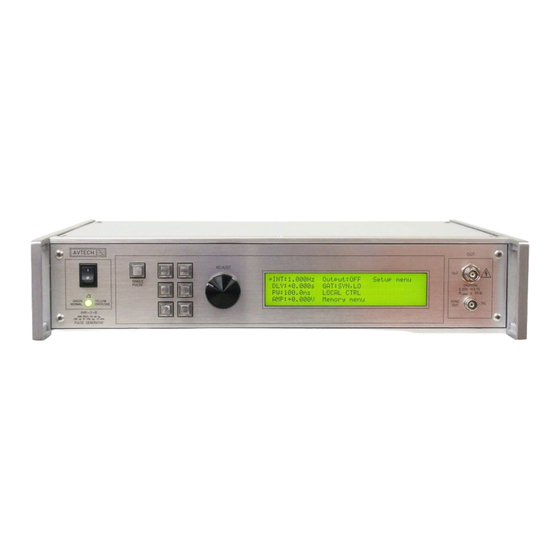
Page 16: Front Panel Controls
FRONT PANEL CONTROLS 1. POWER Switch . This is the main power switch. When turning the instrument on, there is normally a delay of 10 seconds before anything is shown on the main display, as the internal operating system boots up. If the main menu does not appear after 30 seconds, turn off the instrument and leave it off for at least 60 seconds before applying power again. - Page 17 5. LIQUID CRYSTAL DISPLAY (LCD) . This LCD is used in conjunction with the keypad to change the instrument settings. Normally, the main menu is displayed, which lists the key adjustable parameters and their current values. The “Programming Manual for -B Instruments” describes the menus and submenus in detail.
-
Page 18: Rear Panel Controls
REAR PANEL CONTROLS GATE TRIG RS-232 GPIB Note: some connectors may be in different positions than shown above, depending on the exact combination of options ordered. 1. AC POWER INPUT . An IEC-320 C14 three-pronged recessed male socket is provided on the back panel for AC power connection to the instrument. One end of the detachable power cord that is supplied with the instrument plugs into this socket. - Page 19 When triggering externally, the instrument can be set such that the output pulse width tracks the pulse width on this input, or the output pulse width can be set independently. 6. GPIB Connector . A standard GPIB cable can be attached to this connector to allow the instrument to be computer-controlled.
-
Page 20: General Information
GENERAL INFORMATION BASIC PULSE CONTROL This instrument can be triggered by its own internal clock or by an external TTL trigger signal. In either case, two output channels respond to the trigger: OUT and SYNC. The OUT channel is the signal that is applied to the load. Its amplitude and pulse width are variable. - Page 21 > 50 ns TRIG TTL LEVELS (external input) (0V and 3V-5V) PROPAGATION DELAY (FIXED) 100 ns, FIXED SYNC OUT 3V, FIXED DELAY > 0 PULSE WIDTH AMPLITUDE, VARIABLE MAIN OUTPUT Figure C As before, if the delay is negative, the order of the SYNC and OUT pulses is reversed. The last figure illustrates the relationship between the signal when an external TTL-level trigger is used in the PW mode.
-
Page 22: Trigger Modes
TRIGGER MODES This instrument has four trigger modes: Internal Trigger: the instrument controls the trigger frequency, and generates the clock internally. External Trigger: the instrument is triggered by an external TTL-level clock on the back-panel TRIG connector. Manual Trigger: the instrument is triggered by the front-panel “SINGLE PULSE” pushbutton. -
Page 23: Electronic Amplitude Control, "-Ea" Option
ELECTRONIC AMPLITUDE CONTROL, "-EA" OPTION The output amplitude can be set to track the voltage on this input. Zero Volts in corresponds to zero amplitude output, and +10V in corresponds to maximum amplitude out. This mode is activated by selecting "Ext Control" on the front-panel amplitude menu, or with the "source:voltage external"... -
Page 24: Operational Check
Then read the “Local Control” section of the “Programming Manual for -B Instruments” thoroughly. The “Local Control” section describes the front panel controls used in this operational check - in particular, the MOVE, CHANGE, and ADJUST controls. REAL-TIME AVTECH OSCILLOSCOPE PULSER SCOPE... - Page 25 The arrow pointer should be pointing at the frequency menu item. If it is not, press the MOVE button until it is. Press the CHANGE button. The frequency submenu will appear. Rotate the ADJUST knob until the frequency is set at 10 kHz. ...
- Page 26 Press MOVE until the arrow pointer is pointing at the “ON” choice. Press CHANGE to return to the main menu. 9. To change the output amplitude: Press the MOVE button until the arrow pointer is pointing at the amplitude menu item.
-
Page 27: Programming Your Pulse Generator
PROGRAMMING YOUR PULSE GENERATOR KEY PROGRAMMING COMMANDS The “Programming Manual for -B Instruments” describes in detail how to connect the pulse generator to your computer, and the programming commands themselves. A large number of commands are available; however, normally you will only need a few of these. -
Page 28: All Programming Commands
ALL PROGRAMMING COMMANDS For more advanced programmers, a complete list of the available commands is given below. These commands are described in detail in the “Programming Manual for -B Instruments”. (Note: this manual also includes some commands that are not implemented in this instrument. - Page 29 :SOURce INTernal | EXTernal | MANual | HOLD | IMMediate *CLS [no query form] *ESE <numeric value> *ESR? [query only] *IDN? [query only] *OPC *SAV 0 | 1 | 2 | 3 [no query form] *RCL 0 | 1 | 2 | 3 [no query form] *RST [no query form]...
-
Page 30: Mechanical Information
There are no user-adjustable internal circuits. For repairs other than fuse replacement, please contact Avtech (info@avtechpulse.com) to arrange for the instrument to be returned to the factory for repair. Service is to be performed solely by qualified service personnel. -
Page 31: Maintenance
MAINTENANCE REGULAR MAINTENANCE This instrument does not require any regular maintenance. On occasion, one or more of the four rear-panel fuses may require replacement. All fuses can be accessed from the rear panel. See the “FUSES” section for details. CLEANING If desired, the interior of the instrument may be cleaned using compressed air to dislodge any accumulated dust. -
Page 32: Wiring Diagrams
WIRING DIAGRAMS WIRING OF AC POWER M ains circuits - haz ardous live. Do not attempt any repairs on this instrument beyond the fuse replacement procedures described in the manual . Contact Av tech if the instrument A3 - BLACK requir es serv icing. -
Page 33: Wiring Of Dc Power
WIRING OF DC POWER M OUNT WIT H 1/2" ST ANDOFFS P1, N1 = 338-2431-ND, 22000uF, 25V x 2 R1,R2 (ON BOT T OM ): 1.8K OY CHS GND B1 - RED (T O ECP) PCB 1 79B, TRIMMED +2 4V, NO OLO +2 4V, NO OLO +2 4, NO OLO +5 V NSY... -
Page 34: Pcb 158R4 - Low Voltage Power Supply
PCB 158R4 - LOW VOLTAGE POWER SUPPLY... -
Page 35: Pcb 197G - High Voltage Dc Power Supply & Discharge
PCB 197G - HIGH VOLTAGE DC POWER SUPPLY & DISCHARGE... -
Page 36: Pcb 183A-S And 183A-P Capacitor Banks
PCB 183A-S AND 183A-P CAPACITOR BANKS 183A-S (SERIES CAPACIT OR BANK) 7 2 00 K -ND, Mfg . 7 2 0 0, 4-4 0 th read stando ff 3 /8" HV + GN D 7 2 00 K -ND, Mfg . 7 2 0 0, 4-4 0 th read stando ff 3 /8" X1 1 7 2 00 K -ND, Mfg . -
Page 37: Pcb 156D - Polarity Control Board (-Pn Units Only)
PCB 156D - POLARITY CONTROL BOARD (-PN UNITS ONLY) R2 8 R2 3 "UV- ON" IS HIGH IF: 1) "UV+ HIGH" IS LOW, AND +1 5 V VC C VC C 2) "POL" IS LOW. R1 9 0 . 1 u F R1 2 R1 6 5 6 K... -
Page 38: Pcb 104F - Keypad / Display Board, 1/3
PCB 104F - KEYPAD / DISPLAY BOARD, 1/3 Amp 5 4 9 9 9 1 0 -1 , 1 0 p in strai g h t h ead er LC D-BU TT LC D-BU TT. SCH SD A SD A SC L SC L GN D... -
Page 39: Pcb 104F - Keypad / Display Board, 2/3
PCB 104F - KEYPAD / DISPLAY BOARD, 2/3 U4 A VC C C1 0 VC C BU T1 VC C 2 . 2 u F C1 5 C1 3 0 . 1 u F 0 . 1 u F 0 . 1 u F 0 . -
Page 40: Pcb 104F - Keypad / Display Board, 3/3
PCB 104F - KEYPAD / DISPLAY BOARD, 3/3 VC C VC C 0 . 1 u F 2 . 2 u F GN D VC C VC C VC C SD A SD A SC L SC L GN D PA D3 PA D4 PC F8 5 7 4 AN (MU ST HA VE "A"... -
Page 41: Main Wiring (-P Units)
MAIN WIRING (-P UNITS) GND (NO OLO) USE 1/2" ST ANDOFFS +1 5V NSY (15 8P) VPRF OP1B MAIN BOARD, PCB 295 C VSPARE N4-N6: UNUSED +5 V P4-P6: 33uF,400V (P7519-ND) R9-R10: UNUSED SYNC R7-R8: 100K OY CONN2 SYNC OLIMEX PCB 1 83A-P +1 5V ON/OFF PG-P... -
Page 42: Main Wiring (-Pn Units)
MAIN WIRING (-PN UNITS) US E 1/2" ST ANDOFFS P1-P3, N1-N3: 33uF,400V (P7519-ND) OLO GND R7-R10: 100K POS OLO PCB 1 83A-P 3HE: 1/4C24-P125 3HE: 1/4C24-P125 PCB 1 97G 3HF/AHF: 1/4C24-P60 PC B 1 97G 3HF/AHF: 1/4C24-P60 197G 197G POS VERSION, HAS: NEG V ERSION, HAS: D2,4,5,7 NORM ORIENT. -
Page 43: Performance Check Sheet
PERFORMANCE CHECK SHEET...
Need help?
Do you have a question about the AVR-AHF-1-B series and is the answer not in the manual?
Questions and answers