
Related Manuals for Huawei BTS3900 V100R003


Summary of Contents for Huawei BTS3900 V100R003
- Page 1 BTS3900 V100R003 Hardware Description Issue Date 2011-02-15 HUAWEI TECHNOLOGIES CO., LTD.
- Page 3 All other trademarks and trade names mentioned in this document are the property of their respective holders. Notice The purchased products, services and features are stipulated by the contract made between Huawei and the customer. All or part of the products, services and features described in this document may not be within the purchase scope or the usage scope.
-
Page 5: About This Document
This describes the changes in the BTS3900 Hardware Description. 2 Exterior of the BTS3900 Cabinet The BTS3900 cabinet is a vertical cabinet, which is designed in compliance with the IEC297 standard. 3 BTS3900 Hardware Configuration Issue 04 (2011-02-15) Huawei Proprietary and Confidential Copyright © Huawei Technologies Co., Ltd. - Page 6 Times New Roman Normal paragraphs are in Times New Roman. Boldface Names of files, directories, folders, and users are in boldface. For example, log in as user root. Huawei Proprietary and Confidential Issue 04 (2011-02-15) Copyright © Huawei Technologies Co., Ltd.
- Page 7 Multi-level menus are in boldface and separated by the ">" signs. For example, choose File > Create > Folder. Keyboard Operations The keyboard operations that may be found in this document are defined as follows. Issue 04 (2011-02-15) Huawei Proprietary and Confidential Copyright © Huawei Technologies Co., Ltd.
- Page 8 Press the primary mouse button twice continuously and quickly without moving the pointer. Drag Press and hold the primary mouse button and move the pointer to a certain position. Huawei Proprietary and Confidential Issue 04 (2011-02-15) Copyright © Huawei Technologies Co., Ltd.
-
Page 9: Table Of Contents
3.7.6 Slot Assignment for the RFUs in a Base Station Working in GSM+LTE Mode.........3-56 3.7.7 Slot Assignment for the RFUs in a Base Station Working in UMTS+LTE Mode......3-61 Issue 04 (2011-02-15) Huawei Proprietary and Confidential Copyright © Huawei Technologies Co., Ltd. - Page 10 5.5.4 Power Cable for the Fan Box.......................5-72 5.5.5 Power Cable for the RFU........................5-72 5.5.6 Power Cable for the GATM.........................5-73 5.6 BTS3900 Transmission Cable........................5-74 5.6.1 E1/T1 Cable............................5-75 5.6.2 FE/GE Cable............................5-77 viii Huawei Proprietary and Confidential Issue 04 (2011-02-15) Copyright © Huawei Technologies Co., Ltd.
- Page 11 5.8.10 Signal Cable for the ELU........................5-90 5.9 BTS3900 RF Cable............................5-90 5.9.1 RF Jumper............................5-91 5.9.2 Inter-RFU RF Signal Cable........................5-91 6 BTS3900 Auxiliary Equipment....................6-1 6.1 PS4890 Cabinet...............................6-2 6.2 EMU................................6-3 6.3 DDF.................................6-3 Issue 04 (2011-02-15) Huawei Proprietary and Confidential Copyright © Huawei Technologies Co., Ltd.
- Page 13 Figure 3-29 Configuration principles for the CPRI ports on the MRFUs (2)............3-33 Figure 3-30 CPRI port connection principles.....................3-34 Figure 3-31 Configuration principles for the CPRI ports on the MRFUs............3-34 Issue 04 (2011-02-15) Huawei Proprietary and Confidential Copyright © Huawei Technologies Co., Ltd.
- Page 14 Figure 4-11 Panel of the WBBPb........................4-18 Figure 4-12 Panel of the WBBPd........................4-18 Figure 4-13 Panel of the LBBPb........................4-20 Figure 4-14 Panel of the LBBPc........................4-20 Figure 4-15 FAN panel............................4-24 Huawei Proprietary and Confidential Issue 04 (2011-02-15) Copyright © Huawei Technologies Co., Ltd.
- Page 15 Figure 4-55 Panel of the power subrack (AC/DC).....................4-76 Figure 5-1 Power cable connections of the BTS3900 (-48 V)................5-9 Figure 5-2 Power cable connections of the BTS3900 (+24 V)................5-10 Issue 04 (2011-02-15) Huawei Proprietary and Confidential xiii Copyright © Huawei Technologies Co., Ltd.
- Page 16 Figure 5-33 Transmission cable connections in a base station in GSM 4E1/T1+LTE FE/GE mode (1)..5-27 Figure 5-34 Transmission cable connections in a base station in GSM 4E1/T1+LTE FE/GE mode (2)..5-28 Huawei Proprietary and Confidential Issue 04 (2011-02-15) Copyright © Huawei Technologies Co., Ltd.
- Page 17 Figure 5-70 CPRI cable connections in a co-cabinet base station with MRFUs and DRFUs/GRFUs....5-48 Figure 5-71 Dual-star topology over CPRI ports....................5-49 Figure 5-72 CPRI cable connections in co-cabinet mode..................5-49 Issue 04 (2011-02-15) Huawei Proprietary and Confidential Copyright © Huawei Technologies Co., Ltd.
- Page 18 Figure 5-111 In-position signal cable for the PSU (DC/DC)................5-83 Figure 5-112 Monitoring signal cable for the fan box..................5-84 Figure 5-113 Fan box cascade signal cable......................5-85 Figure 5-114 Monitoring signal cable for the EMU...................5-86 Huawei Proprietary and Confidential Issue 04 (2011-02-15) Copyright © Huawei Technologies Co., Ltd.
- Page 19 Figure 5-119 RF jumper.............................5-91 Figure 5-120 Inter-RFU RF signal cable......................5-91 Figure 6-1 Cable connections between the BTS3900 and the PS4890..............6-2 Figure 6-2 Structure of the DDF..........................6-3 Issue 04 (2011-02-15) Huawei Proprietary and Confidential xvii Copyright © Huawei Technologies Co., Ltd.
- Page 21 Table 3-31 Slot assignment for MRFUs and LRFUs in a dual-band base station..........3-49 Table 3-32 Slot assignment for GRFUs (or DRFUs) and WRFUs..............3-51 Table 3-33 Slot assignment for GRFUs (or DRFUs) and WRFUs..............3-52 Issue 04 (2011-02-15) Huawei Proprietary and Confidential Copyright © Huawei Technologies Co., Ltd.
- Page 22 Table 4-29 Ports on the panel of the UEIU......................4-29 Table 4-30 LEDs on the USCU..........................4-30 Table 4-31 LEDs on the TOD port........................4-31 Table 4-32 Ports on the USCU...........................4-31 Table 4-33 Specifications of the UTRP......................4-32 Huawei Proprietary and Confidential Issue 04 (2011-02-15) Copyright © Huawei Technologies Co., Ltd.
- Page 23 Table 5-3 CPRI Cables............................5-6 Table 5-4 Signal Cables............................5-7 Table 5-5 RF Cables.............................5-8 Table 5-6 Power cables of the BTS3900 (-48 V)....................5-10 Table 5-7 Power cables of the BTS3900 (+24 V)....................5-10 Issue 04 (2011-02-15) Huawei Proprietary and Confidential Copyright © Huawei Technologies Co., Ltd.
- Page 24 Table 5-38 Transmission cable connections in a base station in GSM 4E1/T1+LTE FE/GE mode (1)....5-27 Table 5-39 Transmission cable connections in a base station in GSM 4E1/T1+LTE FE/GE mode (2)....5-28 xxii Huawei Proprietary and Confidential Issue 04 (2011-02-15) Copyright © Huawei Technologies Co., Ltd.
- Page 25 Table 5-76 Pin assignment of the fan box cascade signal cable.................5-85 Table 5-77 Pin assignment for the wires of the monitoring signal cable for the EMU........5-86 Issue 04 (2011-02-15) Huawei Proprietary and Confidential xxiii Copyright © Huawei Technologies Co., Ltd.
- Page 26 Table 5-80 Pin assignment for the wires of the signal cable for the ELU............5-90 Table 6-1 Cables between the BTS3900 and the PS4890..................6-2 Table 6-2 Technical specifications of the DDF....................6-4 xxiv Huawei Proprietary and Confidential Issue 04 (2011-02-15) Copyright © Huawei Technologies Co., Ltd.
- Page 27 Compared with issue 02 (2010-08-30), this issue incorporates the following change: Contents Change Description 2 Exterior of the BTS3900 Cabinet The dimensions of the BTS3900 cabinet is added. Compared with issue 02 (2010-08-30), no information is deleted. Issue 04 (2011-02-15) Huawei Proprietary and Confidential Copyright © Huawei Technologies Co., Ltd.
- Page 28 Modification 3.5.1 CPRI Port Specifications LBBPb, LBBPc, and LRFU are added. Compared with issue 01 (2010-05-04), no information is deleted. 01 (2010-05-04) This is the draft release. Huawei Proprietary and Confidential Issue 04 (2011-02-15) Copyright © Huawei Technologies Co., Ltd.
-
Page 29: Exterior Of The Bts3900 Cabinet
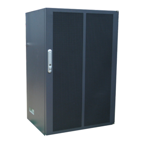
The BTS3900 cabinet is a vertical cabinet, which is designed in compliance with the IEC297 standard. Figure 2-1 shows the exterior of a BTS3900 cabinet. Figure 2-1 Exterior of a BTS3900 cabinet Figure 2-2 shows the dimensions of a BTS3900 cabinet. Issue 04 (2011-02-15) Huawei Proprietary and Confidential Copyright © Huawei Technologies Co., Ltd. -
Page 30: Figure 2-2 Dimensions Of A Bts3900 Cabinet
BTS3900 2 Exterior of the BTS3900 Cabinet Hardware Description Figure 2-2 Dimensions of a BTS3900 cabinet Huawei Proprietary and Confidential Issue 04 (2011-02-15) Copyright © Huawei Technologies Co., Ltd. -
Page 31: Bts3900 Hardware Configuration
UPEU, UEIU, or EMU, so that the entire site can be monitored. 3.7 RF Configurations The RFUs configured in a base station can be DRFUs, GRFUs, WRFUs, LRFUs, or MRFUs. Issue 04 (2011-02-15) Huawei Proprietary and Confidential Copyright © Huawei Technologies Co., Ltd. -
Page 32: Board And Module Configurations
BTS3900 cabinet (+24 V DC), and BTS3900 cabinet (AC). Figure 3-1 Module configurations in the BTS3900 cabinet (-48 V DC) (1) RFU (2) Fan box (3) Air inlet (4) BBU3900 (5) DCDU-01 Huawei Proprietary and Confidential Issue 04 (2011-02-15) Copyright © Huawei Technologies Co., Ltd. -
Page 33: Figure 3-2 Module Configurations In The Bts3900 Cabinet (+24 V Dc)
(3) Air inlet (4) BBU3900 (5) DCDU-01 (6) Power equipment (DC/DC) Figure 3-3 Module configurations in the BTS3900 cabinet (AC) (1) RFU (2) Fan box (3) Air inlet Issue 04 (2011-02-15) Huawei Proprietary and Confidential Copyright © Huawei Technologies Co., Ltd. -
Page 34: Table 3-1 Components In The Cabinet
220 V AC single-phase, 220 V AC (AC/DC) three-phase, and 110 V AC dual-live-wire power into -48 V DC power and provides power to all components in the cabinet. Huawei Proprietary and Confidential Issue 04 (2011-02-15) Copyright © Huawei Technologies Co., Ltd. -
Page 35: Board Configurations Of The Bbu3900
Figure 3-4. Figure 3-4 Slots in the BBU3900 BBU3900 in GO Mode Table 3-2 describes the principles for configuring the boards in the BBU3900 in GO mode. Issue 04 (2011-02-15) Huawei Proprietary and Confidential Copyright © Huawei Technologies Co., Ltd. -
Page 36: Figure 3-5 Typical Configuration Of The Bbu3900 In Go Mode
Figure 3-5 Typical configuration of the BBU3900 in GO mode BBU3900 in UO Mode Table 3-3 describes the principles for configuring the boards in the BBU3900 in UO mode. Huawei Proprietary and Confidential Issue 04 (2011-02-15) Copyright © Huawei Technologies Co., Ltd. -
Page 37: Table 3-3 Principles For Configuring The Boards In The Bbu3900 In Uo Mode
Optional Slot 0, slot 1, Configured in a slot 4, and slot 5 slot, with slot priority of slot 4, slot 5, slot 0, and slot 1 Issue 04 (2011-02-15) Huawei Proprietary and Confidential Copyright © Huawei Technologies Co., Ltd. -
Page 38: Figure 3-6 Typical Configuration Of The Bbu3900 In Uo Mode
Mandatory Slots 0 to 3 Configured in a slot, with slot priority of slot 3, slot 1, and slot 2 in the case of a single LBBP Huawei Proprietary and Confidential Issue 04 (2011-02-15) Copyright © Huawei Technologies Co., Ltd. -
Page 39: Figure 3-7 Typical Configuration Of The Bbu3900 In Lo Mode
0 is also occupied) Figure 3-7 shows the typical configurations of the BBU3900 in LO mode. Figure 3-7 Typical configuration of the BBU3900 in LO mode Issue 04 (2011-02-15) Huawei Proprietary and Confidential Copyright © Huawei Technologies Co., Ltd. -
Page 40: Table 3-5 Principles For Configuring The Boards In The Bbu3900 In Gu Mode
Slot 0 or slot 1 Preferentially configured in slot 1 Configured in slot 1 in the case of 1 U dual- satellite-card (in this case, slot 0 is also occupied) 3-10 Huawei Proprietary and Confidential Issue 04 (2011-02-15) Copyright © Huawei Technologies Co., Ltd. -
Page 41: Figure 3-8 Typical Configuration Of The Bbu3900 In Gu Mode
Slots 0 to 3 Configured in a slot, with slot priority of slot 3, slot 1, and slot 2 Mandatory Slot 16 Configured only in slot 16 Issue 04 (2011-02-15) Huawei Proprietary and Confidential 3-11 Copyright © Huawei Technologies Co., Ltd. -
Page 42: Figure 3-9 Typical Configuration Of The Bbu3900 In Gl Mode
Figure 3-9 shows the typical configurations of the BBU3900 in GL mode. Figure 3-9 Typical configuration of the BBU3900 in GL mode 3-12 Huawei Proprietary and Confidential Issue 04 (2011-02-15) Copyright © Huawei Technologies Co., Ltd. -
Page 43: Table 3-7 Principles For Configuring The Boards In The Bbu3900 In Ul Mode
4, slot 5, slot 0, and slot 1 The slot priority of the UO UTRP is higher than that of the LO UTRP Issue 04 (2011-02-15) Huawei Proprietary and Confidential 3-13 Copyright © Huawei Technologies Co., Ltd. -
Page 44: Combinations Of Cabinets
The secondary cabinet is the cabinet that is not configured with the BBU. Figure 3-11, Figure 3-12, and Figure 3-13 show the side-by-side installation mode with two cabinets. 3-14 Huawei Proprietary and Confidential Issue 04 (2011-02-15) Copyright © Huawei Technologies Co., Ltd. -
Page 45: Figure 3-11 Two Bts3900 (-48 V Dc) Cabinets Installed Side By Side
3 BTS3900 Hardware Configuration Figure 3-11 Two BTS3900 (-48 V DC) cabinets installed side by side Figure 3-12 Two BTS3900 (+24 V DC) cabinets installed side by side Issue 04 (2011-02-15) Huawei Proprietary and Confidential 3-15 Copyright © Huawei Technologies Co., Ltd. -
Page 46: Figure 3-13 Two Bts3900 (Ac) Cabinets Installed Side By Side
The stacking of the BTS3900 (AC) cabinets is not recommended. If cabinets are stacked, the highest operating temperature of the cabinets is 50°C. Figure 3-14 Figure 3-15 show the stack mode with two cabinets. 3-16 Huawei Proprietary and Confidential Issue 04 (2011-02-15) Copyright © Huawei Technologies Co., Ltd. -
Page 47: Figure 3-14 Two Stacked Bts3900 (-48 V Dc) Cabinets
BTS3900 Hardware Description 3 BTS3900 Hardware Configuration Figure 3-14 Two stacked BTS3900 (-48 V DC) cabinets Issue 04 (2011-02-15) Huawei Proprietary and Confidential 3-17 Copyright © Huawei Technologies Co., Ltd. -
Page 48: Power System Of The Bts3900
Table 3-8 Applicable AC input voltage ranges Power Input Type Rated Voltage Working Voltage 220 V AC single-phase 220 V AC to 240 V AC 176 V AC to 290 V AC 3-18 Huawei Proprietary and Confidential Issue 04 (2011-02-15) Copyright © Huawei Technologies Co., Ltd. -
Page 49: Configurations Of The Upper-Level Circuit Breaker And Power Cables
≤ 15 m 25 mm 200 V AC single- 1 x 63 A or 1 x 50 A ≤ 40 m 6 mm phase (both using the two- Issue 04 (2011-02-15) Huawei Proprietary and Confidential 3-19 Copyright © Huawei Technologies Co., Ltd. -
Page 50: Power Distribution Of The Bts3900
V DC) cabinet, and the DCDU-01 feeds power to each module in the BTS3900 cabinet. Figure 3-16 shows the power distribution principles. Figure 3-16 Power distribution of the BTS3900 (-48 V DC) cabinet NOTE MCB: miniature circuit breaker 3-20 Huawei Proprietary and Confidential Issue 04 (2011-02-15) Copyright © Huawei Technologies Co., Ltd. -
Page 51: Figure 3-17 Power Distribution Of The Bts3900 (+24 V Dc) Cabinet
AC power into -48 V DC power and feeds the -48 V DC power to the DCDU-01. The DCDU-01 feeds power to each module in the cabinet. Figure 3-18 shows the power distribution principles. Figure 3-18 Power distribution of the BTS3900 (AC) cabinet Issue 04 (2011-02-15) Huawei Proprietary and Confidential 3-21 Copyright © Huawei Technologies Co., Ltd. -
Page 52: Transmission Board Configurations
GTMU/ 10 Mbit/s and over FE/GE GTMUb 100 Mbit/s electrical cable LMPT 10 Mbit/s, 100 Mbit/s, and 1000 Mbit/s WMPT UMTS 10 Mbit/s and 100 Mbit/s 3-22 Huawei Proprietary and Confidential Issue 04 (2011-02-15) Copyright © Huawei Technologies Co., Ltd. -
Page 53: Cpri Port Configurations
3.5.1 CPRI Port Specifications The base station configurations are affected by the number, transmission rate, and supported topology of CPRI ports on the RFUs and BBU. Issue 04 (2011-02-15) Huawei Proprietary and Confidential 3-23 Copyright © Huawei Technologies Co., Ltd. -
Page 54: Table 3-12 Specifications Of The Cpri Ports On The Boards In The Bbu
1.25 Gbit/s Star or chain WRFU 1.25 Gbit/s or 2.5 Star or chain Gbit/s MRFU 1.25 Gbit/s Star MRFU V2 1.25 Gbit/s or 2.5 Star Gbit/s 3-24 Huawei Proprietary and Confidential Issue 04 (2011-02-15) Copyright © Huawei Technologies Co., Ltd. -
Page 55: Configuration Principles For The Cpri Ports On The Rfu In The Gsm Only Base Station
The CPRI port configuration principles in a base station with a single cabinet are shown in Figure 3-20 and listed in Table 3-14. The CPRI ports corresponding to an idle slot in the cabinet are idle. Issue 04 (2011-02-15) Huawei Proprietary and Confidential 3-25 Copyright © Huawei Technologies Co., Ltd. -
Page 56: Figure 3-20 Configuration Principles For The Cpri Ports In A Single Cabinet
Port on GTMU The CPRI port configuration principles in a base station with two cabinets are shown in Figure 3-21 and listed in Table 3-15 Table 3-16. 3-26 Huawei Proprietary and Confidential Issue 04 (2011-02-15) Copyright © Huawei Technologies Co., Ltd. -
Page 57: Configuration Principles For The Cpri Ports On The Rfu In The Umts Only Base Station
UMTS Only Base Station When a base station works in UMTS mode, the WRFUs in the slots of the cabinet are connected to the WBBPbs/WBBPds in the BBU. Issue 04 (2011-02-15) Huawei Proprietary and Confidential 3-27 Copyright © Huawei Technologies Co., Ltd. -
Page 58: Figure 3-22 Cpri Port Connection Principles
The CPRI port configuration principles in a base station configured with WBBPbs are shown in Figure 3-23 and listed in Table 3-17. Figure 3-23 CPRI port configuration principles (1) 3-28 Huawei Proprietary and Confidential Issue 04 (2011-02-15) Copyright © Huawei Technologies Co., Ltd. -
Page 59: Configuration Principles For The Cpri Ports On The Rfu In The Lte Only Base Station
3.5.4 Configuration Principles for the CPRI Ports on the RFU in the LTE Only Base Station When a base station works in LTE only mode, the RFUs in the cabinet are the LRFUs. Issue 04 (2011-02-15) Huawei Proprietary and Confidential 3-29 Copyright © Huawei Technologies Co., Ltd. -
Page 60: Figure 3-25 Cpri Port Connection Principles
The CPRI port configuration principles are shown in Figure 3-26 and listed in Table 3-19. Figure 3-26 CPRI port configuration principles Table 3-19 CPRI port configuration principles LRFU Slot Number 3-30 Huawei Proprietary and Confidential Issue 04 (2011-02-15) Copyright © Huawei Technologies Co., Ltd. -
Page 61: Configuration Principles For The Cpri Ports On The Rfu In The Gsm+Umts Base Station
The CPRI1 port on the MRFU is connected to the WBBPb or WBBPd for UMTS data transmission. The configuration principles for the CPRI ports on the MRFUs are as follows: Issue 04 (2011-02-15) Huawei Proprietary and Confidential 3-31 Copyright © Huawei Technologies Co., Ltd. -
Page 62: Table 3-20 Configuration Principles For The Cpri Ports On The Mrfus (1)
WBBPb in Slot2 – The CPRI port configuration principles in a base station configured with WBBPds are shown in Figure 3-29 and listed in Table 3-21. 3-32 Huawei Proprietary and Confidential Issue 04 (2011-02-15) Copyright © Huawei Technologies Co., Ltd. -
Page 63: Configuration Principles For The Cpri Ports On The Rfu In The Gsm+Lte Base Station
CPRI links. MRFUs cannot be connected to RRUs. Figure 3-30 shows the CPRI port connection principles for the MRFUs working in GSM+LTE mode. Issue 04 (2011-02-15) Huawei Proprietary and Confidential 3-33 Copyright © Huawei Technologies Co., Ltd. -
Page 64: Figure 3-30 Cpri Port Connection Principles
3-22. Figure 3-31 Configuration principles for the CPRI ports on the MRFUs Table 3-22 Configuration principles for the CPRI ports on the MRFUs MRFU Slot Number 3-34 Huawei Proprietary and Confidential Issue 04 (2011-02-15) Copyright © Huawei Technologies Co., Ltd. -
Page 65: Configuration Principles For The Cpri Ports On The Rfu In The Umts+Lte Base Station
The LRFUs use the configuration principles for the CPRI ports on RFUs in LTE mode. The CPRI port connection principles in UMTS+LTE mode are shown in Figure 3-32 and listed Table 3-23. Figure 3-32 CPRI port configuration principles Issue 04 (2011-02-15) Huawei Proprietary and Confidential 3-35 Copyright © Huawei Technologies Co., Ltd. -
Page 66: Bts3900 Monitoring System
The BBU houses the UPEU and UEIU for monitoring. Each board has two Boolean input ports and two RS485 input ports, and each Boolean input port receives four Boolean inputs. Figure 3-33 shows the slot assignment for the UPEU and UEIU. 3-36 Huawei Proprietary and Confidential Issue 04 (2011-02-15) Copyright © Huawei Technologies Co., Ltd. -
Page 67: Monitoring Principles Of The Cabinet
MON port on the BBU. It collects the alarms of all components and reports the alarms to the BBU by using the RS485 serial bus. Issue 04 (2011-02-15) Huawei Proprietary and Confidential 3-37 Copyright © Huawei Technologies Co., Ltd. -
Page 68: Figure 3-34 Monitoring System For The Bts3900 Cabinet (-48 V Dc)
Figure 3-34 Monitoring system for the BTS3900 cabinet (-48 V DC) Figure 3-35 Monitoring system for the BTS3900 cabinet (+24 V DC) 3-38 Huawei Proprietary and Confidential Issue 04 (2011-02-15) Copyright © Huawei Technologies Co., Ltd. -
Page 69: Customized Alarm Inputs
Monitoring Board Alarm Inputs -48 V DC cabinet or None UPEU AC cabinet 1 to 16 UPEU+UEIU 17 to 32 UPEU+UEIU+EMU +24 V DC cabinet None UPEU Issue 04 (2011-02-15) Huawei Proprietary and Confidential 3-39 Copyright © Huawei Technologies Co., Ltd. -
Page 70: Figure 3-37 Customized Alarms Collected By The Upeu Or Ueiu
The cable connection of the EMU in the BTS3900 cabinet (-48 V DC) and BTS3900 cabinet (+24 V DC): The EMU is connected to the MON1 port on the UPEU in the BBU. 3-40 Huawei Proprietary and Confidential Issue 04 (2011-02-15) Copyright © Huawei Technologies Co., Ltd. -
Page 71: Rf Configurations
When a base station works in GSM+LTE mode, the RFU slot assignment in a cabinet must comply with specific principles. 3.7.7 Slot Assignment for the RFUs in a Base Station Working in UMTS+LTE Mode Issue 04 (2011-02-15) Huawei Proprietary and Confidential 3-41 Copyright © Huawei Technologies Co., Ltd. -
Page 72: Rfu Configurations
1T2R (GU) MRFU V2 working in GSM+UMTS mode supports a maximum of six carriers, and a maximum of two carriers are supported by the UMTS side. 3-42 Huawei Proprietary and Confidential Issue 04 (2011-02-15) Copyright © Huawei Technologies Co., Ltd. -
Page 73: Slot Assignment For The Rfus In A Base Station Working In Gsm Only Mode
Scenario 1: A single-band base station supporting not more than three sectors for the band, with the configuration of GRFUs or DRFUs in a single RFC Issue 04 (2011-02-15) Huawei Proprietary and Confidential 3-43 Copyright © Huawei Technologies Co., Ltd. -
Page 74: Figure 3-39 Gsm S4/4/4 (1G+1G+1G)
If more than three single-band sectors are configured in a single RFC, GRFUs or DRFUs are positioned in the slots from left to right in the RFC. 3-44 Huawei Proprietary and Confidential Issue 04 (2011-02-15) Copyright © Huawei Technologies Co., Ltd. -
Page 75: Figure 3-41 Gsm S4/4/4 & S4/4/4 (1G+1G+1G & 1G+1G+1G)
Slot 0 or 1 Slot 2 or 3 Slot 4 or 5 Cabinet 2 Slot 1 or 2 Slot 2 or 3 Slot 4 or 5 Issue 04 (2011-02-15) Huawei Proprietary and Confidential 3-45 Copyright © Huawei Technologies Co., Ltd. -
Page 76: Slot Assignment For The Rfus In A Base Station Working In Umts Only Mode
A slot can be identified through cabinet number+slot number, for example, slot 1 in cabinet 1 (primary RFC). Principles for RFU Slot Assignment Scenario 1: Three WRFUs for three sectors 3-46 Huawei Proprietary and Confidential Issue 04 (2011-02-15) Copyright © Huawei Technologies Co., Ltd. -
Page 77: Slot Assignment For The Rfus In A Base Station Working In Lte Only Mode
LTE Only Mode When a base station works in LTE only mode, the LRFU or MRFU slot assignment in a cabinet must comply with specific principles. Issue 04 (2011-02-15) Huawei Proprietary and Confidential 3-47 Copyright © Huawei Technologies Co., Ltd. -
Page 78: Figure 3-45 Lrfu 2T2R 3 X 20 Mhz
Slot 0 or 1 in cabinet Slot 2 or 3 in cabinet Slot 4 or 5 in cabinet Figure 3-45 LRFU 2T2R 3 x 20 MHz 3-48 Huawei Proprietary and Confidential Issue 04 (2011-02-15) Copyright © Huawei Technologies Co., Ltd. -
Page 79: Figure 3-46 Lrfu 4T4R 3 X 20 Mhz
Slot 4 or 5 in cabinet in cabinet in cabinet MRFU Slot 0 or 1 Slot 2 or 3 Slot 4 or 5 in cabinet in cabinet in cabinet Issue 04 (2011-02-15) Huawei Proprietary and Confidential 3-49 Copyright © Huawei Technologies Co., Ltd. -
Page 80: Slot Assignment For The Rfus In A Base Station Working In Gsm+Umts Mode
+UMTS 900M S1/1/1, four GSM sectors and three UMTS sectors are configured. In this case, MRFUs rather than GRFUs or DRFUs must be configured for the GSM sectors. 3-50 Huawei Proprietary and Confidential Issue 04 (2011-02-15) Copyright © Huawei Technologies Co., Ltd. -
Page 81: Table 3-32 Slot Assignment For Grfus (Or Drfus) And Wrfus
Table 3-32 Slot assignment for GRFUs (or DRFUs) and WRFUs Sector Number Cabinet 1 Slot 0 Slot 2 Slot 4 Slot 1 Slot 3 Slot 5 Cabinet 2 Issue 04 (2011-02-15) Huawei Proprietary and Confidential 3-51 Copyright © Huawei Technologies Co., Ltd. -
Page 82: Figure 3-48 Gsm 900M S4/4/4+Umts 1800M S1/1/1
Table 3-33 Slot assignment for GRFUs (or DRFUs) and WRFUs Secto Cabin Slot 0 Slot 1 Slot 2 Slot 3 Slot 4 Slot 5 et 1 Cabin Slot 1 Slot 3 Slot 5 et 2 3-52 Huawei Proprietary and Confidential Issue 04 (2011-02-15) Copyright © Huawei Technologies Co., Ltd. -
Page 83: Figure 3-49 Gsm S4/4/4 & S4/4/4+Umts 1800M S1/1/1
MRFUs are positioned in slots 1, 3, and 5 in cabinet 1. Table 3-34 RFU slot assignment for MRFUs Sector Number Cabinet 1 Slot 0 Slot 2 Slot 4 Slot 1 Slot 3 Slot 5 Cabinet 2 Issue 04 (2011-02-15) Huawei Proprietary and Confidential 3-53 Copyright © Huawei Technologies Co., Ltd. -
Page 84: Figure 3-50 Gsm S4/2/2 & S4/4/4+Umts 900M S1/1/1
Slot 0 or 1 Slot 2 or 3 Slot 4 or 5 Cabinet 2 Slot 0 or 1 Slot 2 or 3 Slot 4 or 5 3-54 Huawei Proprietary and Confidential Issue 04 (2011-02-15) Copyright © Huawei Technologies Co., Ltd. -
Page 85: Table 3-36 Rfu Slot Assignment For Mrfus, Grfus (Or Drfus), And Wrfus
Slot 1 Slot 2 Slot 3 Slot 4 Slot 5 et 1 Cabin Slot 0 Slot 2 Slot 4 et 2 or 1 or 3 or 5 Issue 04 (2011-02-15) Huawei Proprietary and Confidential 3-55 Copyright © Huawei Technologies Co., Ltd. -
Page 86: Slot Assignment For The Rfus In A Base Station Working In Gsm+Lte Mode
The sectors in a base station working in GSM only mode are numbered from G1 in a numerical order, for example G1 and G2. Low-frequency sectors are numbered from G1 to G6, and high-frequency sectors are numbered from G7 to G12. 3-56 Huawei Proprietary and Confidential Issue 04 (2011-02-15) Copyright © Huawei Technologies Co., Ltd. -
Page 87: Figure 3-53 Mrfu900M 2T2R 3 X 20 Mhz+Mrfu1800M 2T2R 3 X 20 Mhz
Cabinet 2 Slot 0 or 1 Slot 2 or 3 Slot 4 or 5 Figure 3-53 MRFU900M 2T2R 3 x 20 MHz+MRFU1800M 2T2R 3 x 20 MHz Issue 04 (2011-02-15) Huawei Proprietary and Confidential 3-57 Copyright © Huawei Technologies Co., Ltd. -
Page 88: Figure 3-54 Mrfu900M 2T2R 3 X 20 Mhz+6Grfu1800M
Slot 0 or 1 Slot 2 or 3 Slot 4 or 5 Cabinet 2 Slot 0 or 1 Slot 2 or 3 Slot 4 or 5 3-58 Huawei Proprietary and Confidential Issue 04 (2011-02-15) Copyright © Huawei Technologies Co., Ltd. -
Page 89: Figure 3-55 3 X 20 Mhz 2T2R
Slot 0 or 1 Slot 2 or 3 Slot 4 or 5 Cabinet 2 Slot 0 or 1 Slot 2 or 3 Slot 4 or 5 Issue 04 (2011-02-15) Huawei Proprietary and Confidential 3-59 Copyright © Huawei Technologies Co., Ltd. -
Page 90: Figure 3-56 3Grfu+Lrfu 3 X 20 Mhz
Slot 2 Slot 4 et 1 or 1 or 3 or 5 Cabin Slot 0 Slot 2 Slot 4 Slot 1 Slot 3 Slot 5 et 2 3-60 Huawei Proprietary and Confidential Issue 04 (2011-02-15) Copyright © Huawei Technologies Co., Ltd. -
Page 91: Slot Assignment For The Rfus In A Base Station Working In Umts+Lte Mode
A slot can be identified through cabinet number+slot number, for example, slot 1 in cabinet 1 (primary RFC). Principles for RFU Slot Assignment Scenario 1: A dual-mode base station, with the configuration of WRFUs and LRFUs Issue 04 (2011-02-15) Huawei Proprietary and Confidential 3-61 Copyright © Huawei Technologies Co., Ltd. -
Page 92: Figure 3-58 Umts S1/1/1+Lte 3 X 20 Mhz
Slot 0 or 1 Slot 2 or 3 Slot 4 or 5 Cabinet 2 Slot 1 Slot 3 Slot 5 Figure 3-58 UMTS S1/1/1+LTE 3 x 20 MHz 3-62 Huawei Proprietary and Confidential Issue 04 (2011-02-15) Copyright © Huawei Technologies Co., Ltd. -
Page 93: Bts3900 Components
A fan box consists of a fan tray, four fans, and an FMU. 4.9 GATM The GSM Antenna and TMA control Module (GATM) controls the antenna and TMA. 4.10 ELU Issue 04 (2011-02-15) Huawei Proprietary and Confidential Copyright © Huawei Technologies Co., Ltd. - Page 94 The power equipment (DC/DC) converts +24 V DC power into -48 V DC power. 4.12 Power Equipment (AC/DC) The power equipment (AC/DC) converts 220 V AC power into -48 V DC power. Huawei Proprietary and Confidential Issue 04 (2011-02-15) Copyright © Huawei Technologies Co., Ltd.
-
Page 95: Bbu3900 Equipment
If there is a label on the FAN unit of the BBU, the ESN is printed on a label and the mounting ears of the BBU. Figure 4-2 shows the position of the ESN. Issue 04 (2011-02-15) Huawei Proprietary and Confidential Copyright © Huawei Technologies Co., Ltd. -
Page 96: Boards And Module Of The Bbu3900
Panel The GTMU is classified into two types: GTMU and GTMUb. Figure 4-4 Figure 4-5 show the panels of the GTMU and GTMUb. Huawei Proprietary and Confidential Issue 04 (2011-02-15) Copyright © Huawei Technologies Co., Ltd. -
Page 97: Figure 4-4 Gtmu Panel
Four IDX2 ports on the backplane of the GTMUb can achieve the function of baseband resource pool backup. LEDs Table 4-1 describes the LEDs on the GTMU. Issue 04 (2011-02-15) Huawei Proprietary and Confidential Copyright © Huawei Technologies Co., Ltd. -
Page 98: Table 4-1 Leds On The Gtmu
CPRI0 to CPRI5 Green The CPRI link is functional. The optical module fails to receive signals. Green (LINK LED The connection is set on the left) up successfully. Huawei Proprietary and Confidential Issue 04 (2011-02-15) Copyright © Huawei Technologies Co., Ltd. -
Page 99: Table 4-3 Ports On The Gtmu
CPRI0 to CPRI5 SFP female Data transmission port interconnected to the RFU. It supports the input and output of optical and electrical transmission signals EXT (GTMUb) SFP female Obligate Issue 04 (2011-02-15) Huawei Proprietary and Confidential Copyright © Huawei Technologies Co., Ltd. -
Page 100: Table 4-4 Details Of The Dip Switch S1
Switch The E1 resistance is set to 75 ohm. The E1 resistance is set to 120 ohm. The T1 resistance is set to 100 ohm. Others Unavailable Huawei Proprietary and Confidential Issue 04 (2011-02-15) Copyright © Huawei Technologies Co., Ltd. -
Page 101: Table 4-5 Details Of The Dip Switch S2
Table 4-7 Details of the DIP Switch S5 Bit Status Description Switch Not supporting E1 bypass Supporting E1 bypass of level-1 cascaded base stations Supporting E1 bypass of level-2 cascaded base stations Issue 04 (2011-02-15) Huawei Proprietary and Confidential Copyright © Huawei Technologies Co., Ltd. -
Page 102: Figure 4-6 Panel Of The Wmpt
Provides four E1s/T1s which support ATM and IP protocols Provides one FE electrical port and one FE optical port which support the IP protocol 4-10 Huawei Proprietary and Confidential Issue 04 (2011-02-15) Copyright © Huawei Technologies Co., Ltd. -
Page 103: Figure 4-7 Leds Beside The Three Ports On The Wmpt
Figure 4-7 shows the LEDs beside the three ports. Figure 4-7 LEDs beside the three ports on the WMPT Table 4-9 describes the LEDs and their status. Issue 04 (2011-02-15) Huawei Proprietary and Confidential 4-11 Copyright © Huawei Technologies Co., Ltd. -
Page 104: Table 4-9 Leds And Their Status
Table 4-10 Ports on the WMPT panel Label Connector Type Description E1/T1 DB26 connector E1/T1 port RJ45 connector FE electrical port SFP connector FE optical port SMA connector Obligate 4-12 Huawei Proprietary and Confidential Issue 04 (2011-02-15) Copyright © Huawei Technologies Co., Ltd. -
Page 105: Figure 4-8 Dip Switches On The Wmpt
SW1 and SW2. Table 4-11 Settings of SW1 DIP Status Description Switch T1 Mode The E1 impedance is set to 120 ohms. Issue 04 (2011-02-15) Huawei Proprietary and Confidential 4-13 Copyright © Huawei Technologies Co., Ltd. -
Page 106: Figure 4-9 Lmpt
OM and signaling processing and provides the clock for the BBU3900. Panel Figure 4-9 shows the LMPT. Figure 4-9 LMPT LMPT FE/GE0 FE/GE1 LMPTb USB TST SFP 0 SFP 1 4-14 Huawei Proprietary and Confidential Issue 04 (2011-02-15) Copyright © Huawei Technologies Co., Ltd. -
Page 107: Table 4-13 Leds On The Panel Of The Lmpt
Green The board works in active mode. The board works in standby mode. Blinking (on for The OML link is disrupted. 0.125s and off for 0.125s) Issue 04 (2011-02-15) Huawei Proprietary and Confidential 4-15 Copyright © Huawei Technologies Co., Ltd. -
Page 108: Table 4-14 Ports And Leds
FE/GE0 to FE/GE1 Green (LINK) The connection is set up successfully. No connection is set Orange (ACT) Blinking Data is being transmitted. No data is being transmitted. 4-16 Huawei Proprietary and Confidential Issue 04 (2011-02-15) Copyright © Huawei Technologies Co., Ltd. -
Page 109: Figure 4-10 Panel Of The Wbbpa
The WCDMA Baseband Process Unit (WBBP) of the BBU3900 processes baseband signals. Panels The WBBP has three types of panels, as shown in Figure 4-10, Figure 4-11 Figure 4-12. Figure 4-10 Panel of the WBBPa Issue 04 (2011-02-15) Huawei Proprietary and Confidential 4-17 Copyright © Huawei Technologies Co., Ltd. -
Page 110: Figure 4-11 Panel Of The Wbbpb
UL CE Number DL CE Number WBBPa WBBPb1 WBBPb2 WBBPb3 WBBPb4 WBBPd1 WBBPd2 WBBPd3 LEDs Table 4-17 describes the LEDs on the WBBP and their status. 4-18 Huawei Proprietary and Confidential Issue 04 (2011-02-15) Copyright © Huawei Technologies Co., Ltd. -
Page 111: Table 4-17 Leds On The Wbbp And Their Status
The CPRI link is out one second and OFF of lock. for one second) The SFP module is not in position or the optical module is powered off. Issue 04 (2011-02-15) Huawei Proprietary and Confidential 4-19 Copyright © Huawei Technologies Co., Ltd. -
Page 112: Figure 4-13 Panel Of The Lbbpb
Figure 4-14 Panel of the LBBPc LBBP RX TX RX TX RX TX RX TX RX TX LBBPc CPRI 5 CPRI 0 CPRI 1 CPRI 2 CPRI 3 CPRI 4 4-20 Huawei Proprietary and Confidential Issue 04 (2011-02-15) Copyright © Huawei Technologies Co., Ltd. -
Page 113: Table 4-21 Specifications Of The Lbbp
Antenna Cell Configuration LBBPc 2T2R 4T4R 4T4R 8T8R There are three LEDs on the panel of the LBBP. Table 4-23 describes the LEDs on the LBBP. Issue 04 (2011-02-15) Huawei Proprietary and Confidential 4-21 Copyright © Huawei Technologies Co., Ltd. -
Page 114: Table 4-23 Leds On The Lbbp
Blinking red (on for The RRU in the CPRI 0.125s and off for link has a hardware 0.125s) fault. 4-22 Huawei Proprietary and Confidential Issue 04 (2011-02-15) Copyright © Huawei Technologies Co., Ltd. -
Page 115: Table 4-25 Ports On The Lbbp
It reports the status of the fans and fan unit, and dissipates heat from the BBU. Panels The FAN unit has two types of exterior, which are shown in Figure 4-15 Figure 4-16. Issue 04 (2011-02-15) Huawei Proprietary and Confidential 4-23 Copyright © Huawei Technologies Co., Ltd. -
Page 116: Figure 4-15 Fan Panel
The FANc supports the function of reading and writing the information reported by the electronic label unit. The FAN panel has only one LED, which indicates the operating status of the fans. Table 4-26 describes the LED. 4-24 Huawei Proprietary and Confidential Issue 04 (2011-02-15) Copyright © Huawei Technologies Co., Ltd. -
Page 117: Figure 4-17 Upeua Panel
V DC power into +12 V DC, and the UPEUb converts +24 V DC power into +12 V DC. Figure 4-17, Figure 4-18, and Figure 4-19 show the panels of the UPEUa, UPEUb, and UPEUc respectively. Figure 4-17 UPEUa panel (1) BBU power switch Issue 04 (2011-02-15) Huawei Proprietary and Confidential 4-25 Copyright © Huawei Technologies Co., Ltd. -
Page 118: Figure 4-18 Upeub Panel
Boolean signals. The UPEU has one LED, which indicates the operating status of the UPEU. Table 4-27 describes the LED. 4-26 Huawei Proprietary and Confidential Issue 04 (2011-02-15) Copyright © Huawei Technologies Co., Ltd. -
Page 119: Figure 4-20 Slots In The Bbu
Slot 18 +24 V or Introducing +24 V DC or -48 V DC -48 V power EXT- RJ-45 Port for Boolean inputs 0 to 3 ALM0 Issue 04 (2011-02-15) Huawei Proprietary and Confidential 4-27 Copyright © Huawei Technologies Co., Ltd. -
Page 120: Figure 4-21 Panel Of The Ueiu
The UEIU is configured in slot 18. It provides four ports with two ports transmitting two RS485 input signals and the other two ports transmitting eight Boolean signals. Table 4-29 describes the ports on the panel of the UEIU. 4-28 Huawei Proprietary and Confidential Issue 04 (2011-02-15) Copyright © Huawei Technologies Co., Ltd. -
Page 121: Figure 4-22 Panel Of The Uscub1 (0.5 U)
Figure 4-23 Panel of the USCUb2 (1 U) (1) GPS port (2) RGPS port (3) TOD port (4) M-1PPS port (5) BITS port Functions The USCU has the following functions: Issue 04 (2011-02-15) Huawei Proprietary and Confidential 4-29 Copyright © Huawei Technologies Co., Ltd. -
Page 122: Table 4-30 Leds On The Uscu
USCU and the main control board is enabled. The serial port for communication between the USCU and the main control board is disabled. 4-30 Huawei Proprietary and Confidential Issue 04 (2011-02-15) Copyright © Huawei Technologies Co., Ltd. -
Page 123: Table 4-31 Leds On The Tod Port
BBU3900, the UTRP provides eight E1s/T1s, one unchannelized STM-1/ OC-3 port, four electrical ports, or two optical ports. Specification Table 4-33 describes the specifications of the UTRP. Issue 04 (2011-02-15) Huawei Proprietary and Confidential 4-31 Copyright © Huawei Technologies Co., Ltd. -
Page 124: Figure 4-24 Panel Of The Utrp2 Supporting Two Optical Ports
UTRP6 supporting one STM-1. Figure 4-26 Panel of the UTRP6 supporting one STM-1 Figure 4-27 shows the panel of the UTRP9 supporting four electrical ports. 4-32 Huawei Proprietary and Confidential Issue 04 (2011-02-15) Copyright © Huawei Technologies Co., Ltd. -
Page 125: Figure 4-27 Panel Of The Utrp Supporting Four Electrical Ports
The board is not OFF for 0.125s configured or is loading software. ON for 2s and OFF The board is in the for 2s offline state or under test. Issue 04 (2011-02-15) Huawei Proprietary and Confidential 4-33 Copyright © Huawei Technologies Co., Ltd. -
Page 126: Table 4-35 Leds On The Ethernet Ports Of The Utrp2 And Utrp9
The link is receiving or transmitting data. The link is not receiving or transmitting data. Ports Table 4-36 describes the ports of the UTRP2 supporting two optical ports. 4-34 Huawei Proprietary and Confidential Issue 04 (2011-02-15) Copyright © Huawei Technologies Co., Ltd. -
Page 127: Figure 4-28 Dip Switch On The Utrp3 Or Utrp4
DIP switch on the UTRP3 or UTRP4, Figure 4-29 shows the DIP switch on the UTRPb4. Figure 4-28 DIP switch on the UTRP3 or UTRP4 Issue 04 (2011-02-15) Huawei Proprietary and Confidential 4-35 Copyright © Huawei Technologies Co., Ltd. -
Page 128: Figure 4-29 Dip Switch On The Utrpb4
Other settings of the DIP bits Disabled Table 4-41 DIP switch SW2 on the UTRP DIP Status Description Switch Balanced Mode Unbalanced Mode Other settings of the DIP bits Disabled 4-36 Huawei Proprietary and Confidential Issue 04 (2011-02-15) Copyright © Huawei Technologies Co., Ltd. -
Page 129: Figure 4-30 Panel Of The Ubri
Figure 4-30 Panel of the UBRI Functions The UBRI performs the following functions: Provides extended CPRI optical or electrical ports Performs convergence, distribution, and multi-mode transmission on the CPRI Issue 04 (2011-02-15) Huawei Proprietary and Confidential 4-37 Copyright © Huawei Technologies Co., Ltd. -
Page 130: Table 4-43 Leds On The Panel Of The Ubri
0.125s ON, 0.125s The RRU on the CPRI OFF (Red) link is faulty. 1s ON, 1s OFF (red) The CPRI link is out of lock. 4-38 Huawei Proprietary and Confidential Issue 04 (2011-02-15) Copyright © Huawei Technologies Co., Ltd. -
Page 131: Grfu
The GSM Radio Frequency Unit (GRFU) is designed on the basis of multi-transceiver technology. One GRFU supports 6 carriers. Panel Figure 4-31 shows the GRFU panel. Figure 4-31 GRFU panel Issue 04 (2011-02-15) Huawei Proprietary and Confidential 4-39 Copyright © Huawei Technologies Co., Ltd. -
Page 132: Figure 4-32 Logical Structure Of The Grfu
– Performs down-conversion of the RF signals to IF signals – Amplifies the IF signals and performs IQ demodulation – Performs analog-to-digital conversion through the ADC 4-40 Huawei Proprietary and Confidential Issue 04 (2011-02-15) Copyright © Huawei Technologies Co., Ltd. -
Page 133: Table 4-46 Leds On The Grfu Panel
Therefore, whether the module needs to be replaced cannot be determined. No alarm is generated. Green The module works properly (the TX channel is set to ON). Issue 04 (2011-02-15) Huawei Proprietary and Confidential 4-41 Copyright © Huawei Technologies Co., Ltd. -
Page 134: Table 4-47 Ports On The Grfu Panel
RF RX port, connected to the antenna system ANT_TX/ RF TX/RX port, connected to the antenna system CPRI CPRI0 SFP female Connected to the BBU, or the upper-level RFU during the cascading 4-42 Huawei Proprietary and Confidential Issue 04 (2011-02-15) Copyright © Huawei Technologies Co., Ltd. -
Page 135: Drfu
There are two types of DRFU, that is, the DRFU of 900 MHz and DRFU of 1800 MHz. The panels of the DRFUs are shown in Figure 4-33 Figure 4-34. Issue 04 (2011-02-15) Huawei Proprietary and Confidential 4-43 Copyright © Huawei Technologies Co., Ltd. -
Page 136: Figure 4-33 Panel Of The Drfu Of 900 Mhz
BTS3900 4 BTS3900 Components Hardware Description Figure 4-33 Panel of the DRFU of 900 MHz 4-44 Huawei Proprietary and Confidential Issue 04 (2011-02-15) Copyright © Huawei Technologies Co., Ltd. -
Page 137: Figure 4-34 Panel Of The Drfu Of 1800 Mhz
IF signals. After amplification, analog-to-digital conversion, digital down- conversion, matched filtering, automatic gain control (AGC), the IF signals are sent to the BBU for further processing. Performs power control. Issue 04 (2011-02-15) Huawei Proprietary and Confidential 4-45 Copyright © Huawei Technologies Co., Ltd. -
Page 138: Figure 4-35 Logical Structure Of The Drfu
– Up-converts RF signals to the TX band. The PA amplifies the low-power RF signals that are received from the signal processing unit. The dual-duplexer unit performs the following functions: 4-46 Huawei Proprietary and Confidential Issue 04 (2011-02-15) Copyright © Huawei Technologies Co., Ltd. -
Page 139: Table 4-48 Status Of The Leds On The Drfu
ANT1 and ANT2 ports. No VSWR alarm is reported. CPRI0 Red/Green Steady green The CPRI link is functional. Steady red The optical module fails to receive signals. Issue 04 (2011-02-15) Huawei Proprietary and Confidential 4-47 Copyright © Huawei Technologies Co., Ltd. -
Page 140: Table 4-49 Ports And Sockets On The Drfu
QMA female FIXED Unique port of the DRFU of 1800 MHz, which is used to switch between the UNCOMB combined transmission and divided transmission modes COMB 4-48 Huawei Proprietary and Confidential Issue 04 (2011-02-15) Copyright © Huawei Technologies Co., Ltd. -
Page 141: Wrfu
WCDMA RF signals. After being filtered and amplified or being combined, the RF signals are transmitted through the duplex filter to the antenna for radio transmission. Issue 04 (2011-02-15) Huawei Proprietary and Confidential 4-49 Copyright © Huawei Technologies Co., Ltd. -
Page 142: Figure 4-37 Principle Of The Wrfu
The DL TX channel has the following functions: – Decapsulates the clock signals, control signals, and data signals from the BBU and sends them to associated units – Shapes and filters DL signals 4-50 Huawei Proprietary and Confidential Issue 04 (2011-02-15) Copyright © Huawei Technologies Co., Ltd. -
Page 143: Table 4-50 Leds On The Mrfu Panel
A VSWR-related alarm is generated at OFF for 1s) the ANT_RXB port. Blinking (ON for A VSWR-related alarm is generated at 0.125s and OFF for the ANT_TX/RXA and ANT_RXB 0.125s) ports. Issue 04 (2011-02-15) Huawei Proprietary and Confidential 4-51 Copyright © Huawei Technologies Co., Ltd. -
Page 144: Table 4-51 Ports On The Wrfu Panel
RF antenna channel RX signals RX_OUTA QMA female Output port of diversity signals in the antenna channel Power supply 2V2 power Feeding power socket 4-52 Huawei Proprietary and Confidential Issue 04 (2011-02-15) Copyright © Huawei Technologies Co., Ltd. -
Page 145: Mrfu
One Multi-Mode Radio Frequency Unit (MRFU) supports a maximum of six carriers. Panel Figure 4-38 shows the panel of the MRFU. Figure 4-38 Panel of the MRFU Functions The MRFU has the following functions: Issue 04 (2011-02-15) Huawei Proprietary and Confidential 4-53 Copyright © Huawei Technologies Co., Ltd. -
Page 146: Figure 4-39 Logical Structure Of The Mrfu
– Amplify the IF signals and performing IQ demodulation – Convert analog signals to digital signals – Sample digital signals – Perform matched filtering – Support the digital automatic gain control (DAGC) 4-54 Huawei Proprietary and Confidential Issue 04 (2011-02-15) Copyright © Huawei Technologies Co., Ltd. -
Page 147: Table 4-52 Leds On The Panel Of The Mrfu
On for 1s and off for 1s The module is running (TX channel disabled). VSWR On (red) A VSWR-related alarm is generated at the ANT_TX/RXA port. Issue 04 (2011-02-15) Huawei Proprietary and Confidential 4-55 Copyright © Huawei Technologies Co., Ltd. -
Page 148: Table 4-53 Ports On The Panel Of The Mrfu
MRFU CPRI1 SFP female Connected to the lower-level cascaded connector MRFU Inter-MRFU RX_INB QMA female Input port for diversity receive RF signal port connector 4-56 Huawei Proprietary and Confidential Issue 04 (2011-02-15) Copyright © Huawei Technologies Co., Ltd. -
Page 149: Lrfu
LTE Radio Frequency Units (LRFUs) work in Frequency Division Duplex (FDD) mode. Panel Figure 4-40 shows the panel of the LRFU. Figure 4-40 Panel of the LRFU Issue 04 (2011-02-15) Huawei Proprietary and Confidential 4-57 Copyright © Huawei Technologies Co., Ltd. -
Page 150: Figure 4-41 Logical Structure Of The Lrfu
The control module implements the following functions: Provides the interface for reporting backup power alarms. Provides the functions of the Remote Electrical antenna Tilt (RET) antenna. 4-58 Huawei Proprietary and Confidential Issue 04 (2011-02-15) Copyright © Huawei Technologies Co., Ltd. -
Page 151: Table 4-54 Leds On The Lrfu
On (green) The CPRI links are normal. On (red) The reception of the optical module (or the SFP module) is abnormal, and an alarm is generated. Issue 04 (2011-02-15) Huawei Proprietary and Confidential 4-59 Copyright © Huawei Technologies Co., Ltd. -
Page 152: Dcdu-01
RJ-45 connector Monitoring port Port for monitoring and maintenance 4.7 DCDU-01 The Direct Current Distribution Unit-01 (DCDU-01) supplies DC power to each component in the cabinet. 4-60 Huawei Proprietary and Confidential Issue 04 (2011-02-15) Copyright © Huawei Technologies Co., Ltd. -
Page 153: Figure 4-42 Panel Of The Dcdu-01
RFUs, and fan box Power switch SPARE2, SPARE1, Powering on or powering BBU, FAN, and off the modules such as RFU5 to RFU0 the BBU3900, RFUs, and fan box Issue 04 (2011-02-15) Huawei Proprietary and Confidential 4-61 Copyright © Huawei Technologies Co., Ltd. -
Page 154: Fan Box
Stops the fans when the ambient temperature is low. Figure 4-44 shows the ports on the FMU board. Figure 4-44 Ports on the FMU board Table 4-57 describes the LEDs on the FMU board. 4-62 Huawei Proprietary and Confidential Issue 04 (2011-02-15) Copyright © Huawei Technologies Co., Ltd. -
Page 155: Gatm
4.9 GATM The GSM Antenna and TMA control Module (GATM) controls the antenna and TMA. Panel Figure 4-45 shows the GATM panel. Figure 4-45 GATM panel Issue 04 (2011-02-15) Huawei Proprietary and Confidential 4-63 Copyright © Huawei Technologies Co., Ltd. -
Page 156: Table 4-59 Leds On The Gatm
RET control signals, one is used to connect the GATM to the BBU, and one is used as an extended RS485 port. In addition, there is also a -48 V DC power supply socket. Table 4-60 describes the ports and socket on the GATM. 4-64 Huawei Proprietary and Confidential Issue 04 (2011-02-15) Copyright © Huawei Technologies Co., Ltd. -
Page 157: Elu
+24 V input power cables, -48 V output power cables, monitoring signal cable for the PSU, and in-position signal cable for the PSU respectively. Issue 04 (2011-02-15) Huawei Proprietary and Confidential 4-65 Copyright © Huawei Technologies Co., Ltd. -
Page 158: Components Of The Power Equipment (Dc/Dc)
The PSU is the power supply unit. The PSU (DC/DC) converts +24 V DC power into -48 V DC power. Panel Figure 4-48 shows the panel of the PSU (DC/DC). 4-66 Huawei Proprietary and Confidential Issue 04 (2011-02-15) Copyright © Huawei Technologies Co., Ltd. -
Page 159: Figure 4-48 Panel Of The Psu (Dc/Dc)
Power LED Green The power supply is normal. There is no power input, or the fuse is damaged. Protection LED Yellow The running status is normal. Issue 04 (2011-02-15) Huawei Proprietary and Confidential 4-67 Copyright © Huawei Technologies Co., Ltd. -
Page 160: Power Subrack (Dc/Dc)
(1) Power input wiring (2) PRESENT port (3) ALM port (4) Power output wiring terminals terminals Ports Table 4-63 describes the ports and terminals on the power subrack (DC/DC). 4-68 Huawei Proprietary and Confidential Issue 04 (2011-02-15) Copyright © Huawei Technologies Co., Ltd. -
Page 161: Power Equipment (Ac/Dc)
4.12.1 Components of the Power Equipment (AC/DC) The power equipment (AC/DC) consists of the PMU, PSUs (AC/DC) and power subrack (AC/ DC). Figure 4-50 shows the power equipment (AC/DC). Issue 04 (2011-02-15) Huawei Proprietary and Confidential 4-69 Copyright © Huawei Technologies Co., Ltd. -
Page 162: Pmu
The Power and Environment Monitoring Unit (PMU) performs the power system management, power distribution detection, and alarm reporting functions. Exterior Figure 4-51 shows the PMU. Figure 4-51 PMU 4-70 Huawei Proprietary and Confidential Issue 04 (2011-02-15) Copyright © Huawei Technologies Co., Ltd. -
Page 163: Figure 4-52 Front Panel Of The Pmu
PMU. Table 4-65 Ports and switch on the PMU Port/Switch Function RS232/RS422 port Communicating with the BBU or upper-level PMU Issue 04 (2011-02-15) Huawei Proprietary and Confidential 4-71 Copyright © Huawei Technologies Co., Ltd. -
Page 164: Table 4-66 Leds On The Panel Of The Pmu
Mains overvoltage or undervoltage alarm l Busbar overvoltage or undervoltage alarm l Alarm related to PSUs l Load disconnection alarm No alarm is reported. 4-72 Huawei Proprietary and Confidential Issue 04 (2011-02-15) Copyright © Huawei Technologies Co., Ltd. -
Page 165: Psu (Ac/Dc)
The PSU is a power supply unit. The PSU (AC/DC) converts 220 V AC power into -48 V DC power. Panel Figure 4-54 shows the panel of the PSU (AC/DC). Issue 04 (2011-02-15) Huawei Proprietary and Confidential 4-73 Copyright © Huawei Technologies Co., Ltd. -
Page 166: Figure 4-54 Panel Of The Psu (Ac/Dc)
AC input, or overvoltage and undervoltage of AC input) on the mains, or the PSU has no output. Protection LED Yellow The running status is normal. 4-74 Huawei Proprietary and Confidential Issue 04 (2011-02-15) Copyright © Huawei Technologies Co., Ltd. -
Page 167: Power Subrack (Ac/Dc)
Panel Figure 4-55 shows the panel of the power subrack (AC/DC). Issue 04 (2011-02-15) Huawei Proprietary and Confidential 4-75 Copyright © Huawei Technologies Co., Ltd. -
Page 168: Figure 4-55 Panel Of The Power Subrack (Ac/Dc)
BAT(+) wiring terminal is used for the connection of positive pole for the batteries. Power switch of the batteries The power switch controls the connection of the batteries. 4-76 Huawei Proprietary and Confidential Issue 04 (2011-02-15) Copyright © Huawei Technologies Co., Ltd. -
Page 169: Bts3900 Cables
CPRI cable, signal cable, and RF cable. NOTE The colors of cables vary according to the countries and areas where Huawei products are delivered. If cables are purchased at local market, the colors of the cables must comply with the rules and regulations. - Page 170 FAN unit, BBU alarm cable, and GPS clock signal cable. 5.9 BTS3900 RF Cable The BTS3900 RF cables are the RF jumper and inter-RFU RF signal cable. Huawei Proprietary and Confidential Issue 04 (2011-02-15) Copyright © Huawei Technologies Co., Ltd.
-
Page 171: List Of Bts3900 Cables
5.5.1 Input OT terminal Power input OT terminal External Power wiring power Cable for terminals of supply the Cabinet the power device subrack (AC power (AC/DC) cable) Issue 04 (2011-02-15) Huawei Proprietary and Confidential Copyright © Huawei Technologies Co., Ltd. - Page 172 (DC/DC) 5.5.2 Power OT terminal RTN(+) port OT terminal RTN(+) Cable for on the wiring DCDU-01 terminal for DCDU-01 power output of the power (Black) subrack (AC/DC) Huawei Proprietary and Confidential Issue 04 (2011-02-15) Copyright © Huawei Technologies Co., Ltd.
-
Page 173: Table 5-2 Transmission Cables
5.6.3 FE/GE SFP0 or l FC External Optical connector SFP1 port on connecto transmission Cable the GTMU equipment or WMPT or l SC UTRP connecto l LC connecto Issue 04 (2011-02-15) Huawei Proprietary and Confidential Copyright © Huawei Technologies Co., Ltd. -
Page 174: Table 5-3 Cpri Cables
The CPRI cables between multiple site cabinets may be need to be installed on site according to the configuration. Signal Cables Table 5-4 lists the signal cables. Huawei Proprietary and Confidential Issue 04 (2011-02-15) Copyright © Huawei Technologies Co., Ltd. -
Page 175: Table 5-4 Signal Cables
PSU (DC/DC) 5.8.4 RJ-45 COM IN RJ-45 MON0 port Monitoring connector port on the connector on the UPEU Signal fan box Cable for the Fan Box Issue 04 (2011-02-15) Huawei Proprietary and Confidential Copyright © Huawei Technologies Co., Ltd. -
Page 176: Bts3900 Cable Connections
The cable connections in the BTS3900 vary according to the power supply scenarios and configurations related to the cabinet, transmission system, CPRI port, and RF. 5.2.1 Power Cable Connections This section describes the power cable connections of the BTS3900 cabinet. Huawei Proprietary and Confidential Issue 04 (2011-02-15) Copyright © Huawei Technologies Co., Ltd. -
Page 177: Power Cable Connections
BTS3900 (-48 V). Figure 5-1 Power cable connections of the BTS3900 (-48 V) Table 5-6 lists the power cables of the BTS3900 (-48 V). Issue 04 (2011-02-15) Huawei Proprietary and Confidential Copyright © Huawei Technologies Co., Ltd. -
Page 178: Table 5-6 Power Cables Of The Bts3900 (-48 V)
Table 5-7 Power cables of the BTS3900 (+24 V) Description P1 to P6 For details, see 5.5.5 Power Cable for the RFU. For details, see 5.5.4 Power Cable for the Fan Box. 5-10 Huawei Proprietary and Confidential Issue 04 (2011-02-15) Copyright © Huawei Technologies Co., Ltd. -
Page 179: Figure 5-3 Power Cable Connections Of The Bts3900 (220 V)
BTS3900 (220 V). Table 5-8 Power cables of the BTS3900 (220 V) Description P1 to P6 For details, see 5.5.5 Power Cable for the RFU. Issue 04 (2011-02-15) Huawei Proprietary and Confidential 5-11 Copyright © Huawei Technologies Co., Ltd. -
Page 180: Transmission Cable Connections
E1/T1 cable is used for data transmission in a GSM only base station where the GTMU and UTRP4 are configured as transmission boards in the BBU3900. Figure 5-5 E1/T1 cable connections 5-12 Huawei Proprietary and Confidential Issue 04 (2011-02-15) Copyright © Huawei Technologies Co., Ltd. -
Page 181: Figure 5-6 Fe/Ge Ethernet Cable Connections
Figure 5-7 FE/GE optical cable connections Table 5-12 describes the cable connections. Table 5-12 FE/GE optical cable connections Cable Number Cable Description 5.6.3 FE/GE Optical Cable. Issue 04 (2011-02-15) Huawei Proprietary and Confidential 5-13 Copyright © Huawei Technologies Co., Ltd. -
Page 182: Figure 5-8 E1/T1 Cable Connections (1)
Figure 5-9 E1/T1 cable connections (2) Table 5-14 describes the cable connections. Table 5-14 E1/T1 cable connections (2) Cable Number Cable Description T1 and T2 5.6.1 E1/T1 Cable. 5-14 Huawei Proprietary and Confidential Issue 04 (2011-02-15) Copyright © Huawei Technologies Co., Ltd. -
Page 183: Figure 5-10 Fe/Ge Ethernet Cable Connections (1)
FE/GE optical cable is used for data transmission in a base station where only the WMPT is configured in the BBU. Figure 5-12 FE/GE optical cable connections (1) Issue 04 (2011-02-15) Huawei Proprietary and Confidential 5-15 Copyright © Huawei Technologies Co., Ltd. -
Page 184: Figure 5-13 Fe/Ge Optical Cable Connections (2)
When the E1/T1 cable is used for data transmission, the UTRP is required. Figure 5-14 shows the transmission cable connections. Figure 5-14 E1/T1 cable connections Table 5-19 describes the cable connections. 5-16 Huawei Proprietary and Confidential Issue 04 (2011-02-15) Copyright © Huawei Technologies Co., Ltd. -
Page 185: Figure 5-15 Fe/Ge Optical Cable Connections
BSC and RNC. The GTMU communicates with the WMPT using the backplane to implement TDM common transmission. Figure 5-16 Transmission cable connection for a GSM+UMTS base station in TDM common transmission mode (1) Issue 04 (2011-02-15) Huawei Proprietary and Confidential 5-17 Copyright © Huawei Technologies Co., Ltd. -
Page 186: Figure 5-17 Transmission Cable Connection For A Gsm+Umts Base Station In Tdm Common Transmission Mode
WMPT. The transmission cable connections are similar to Figure 5-18, which are not described here. Figure 5-18 Transmission cable connections for a GSM+UMTS base station in IP over E1 common transmission mode (1) 5-18 Huawei Proprietary and Confidential Issue 04 (2011-02-15) Copyright © Huawei Technologies Co., Ltd. -
Page 187: Figure 5-20 Transmission Cable Connections For A Gsm+Umts Base Station In Ip Over Fe Common Transmission
FE/GE optical ports of the GTMU and the UMTS UTRP2 are interconnected to implement IP co-transmission. Figure 5-20 Transmission cable connections for a GSM+UMTS base station in IP over FE common transmission mode (1) Issue 04 (2011-02-15) Huawei Proprietary and Confidential 5-19 Copyright © Huawei Technologies Co., Ltd. -
Page 188: Figure 5-21 Transmission Cable Connections For A Gsm+Umts Base Station In Ip Over Fe Common Transmission
If the active channel is faulty, the standby channel takes over. After the active channel is restored, the route is switched back to the active one. 5-20 Huawei Proprietary and Confidential Issue 04 (2011-02-15) Copyright © Huawei Technologies Co., Ltd. -
Page 189: Figure 5-22 Transmission Cable Connections With Fe Optical Ports For Interconnection And Fe Electrical Ports
WMPT are interconnected and the FE optical ports on the two boards are connected to the BSC and RNC. Figure 5-23 Transmission cable connections with FE electrical ports for interconnection and FE optical ports connected to the BSC and RNC Issue 04 (2011-02-15) Huawei Proprietary and Confidential 5-21 Copyright © Huawei Technologies Co., Ltd. -
Page 190: Figure 5-24 E1/T1 Cable Connections In Separate Transmission Mode
GSM and UMTS sides when a GSM+UMTS base station works in separate transmission mode. Figure 5-25 FE/GE cable connections in separate transmission mode (1) 5-22 Huawei Proprietary and Confidential Issue 04 (2011-02-15) Copyright © Huawei Technologies Co., Ltd. -
Page 191: Figure 5-26 Fe/Ge Cable Connections In Separate Transmission Mode (2)
LMPT is interconnected to the FE/GE optical port on the GTMU. Figure 5-27 Transmission cable connections for a GSM+LTE base station in IP over E1 common transmission mode (1) Issue 04 (2011-02-15) Huawei Proprietary and Confidential 5-23 Copyright © Huawei Technologies Co., Ltd. -
Page 192: Figure 5-28 Transmission Cable Connections For A Gsm+Lte Base Station In Ip Over E1 Common Transmission
LMPT is interconnected to the FE/GE electrical port on the GTMU. Figure 5-29 Transmission cable connections for a GSM+LTE base station in IP over FE/GE common transmission mode (1) 5-24 Huawei Proprietary and Confidential Issue 04 (2011-02-15) Copyright © Huawei Technologies Co., Ltd. -
Page 193: Figure 5-30 Transmission Cable Connections For A Gsm+Lte Base Station In Ip Over Fe/Ge Common Transmission
If the primary channel is faulty, the secondary channel takes over. After the primary channel is restored, the route is switched back to the primary one. Issue 04 (2011-02-15) Huawei Proprietary and Confidential 5-25 Copyright © Huawei Technologies Co., Ltd. -
Page 194: Figure 5-31 Transmission Cable Connections With Fe Electrical Ports For Interconnection And Fe Optical Ports
FE electrical ports on the two boards are connected to the base station controller. Figure 5-32 Transmission cable connections with FE optical ports for interconnection and FE electrical ports connected to the base station controller 5-26 Huawei Proprietary and Confidential Issue 04 (2011-02-15) Copyright © Huawei Technologies Co., Ltd. -
Page 195: Figure 5-33 Transmission Cable Connections In A Base Station In Gsm 4E1/T1+Lte Fe/Ge Mode (1)
E1/T1 port (providing four E1s/T1s) on the GTMU is used for data transmission on the GSM side and the FE/GE optical port is used for data transmission on the LTE side. Issue 04 (2011-02-15) Huawei Proprietary and Confidential 5-27 Copyright © Huawei Technologies Co., Ltd. -
Page 196: Figure 5-34 Transmission Cable Connections In A Base Station In Gsm 4E1/T1+Lte Fe/Ge Mode (2)
UTRP are used for data transmission on the GSM side and the FE/GE optical port is used for data transmission on the LTE side. 5-28 Huawei Proprietary and Confidential Issue 04 (2011-02-15) Copyright © Huawei Technologies Co., Ltd. -
Page 197: Figure 5-37 Transmission Cable Connections In A Base Station In Gsm Fe/Ge+Lte Fe/Ge Mode (1)
FE/GE electrical port is used for data transmission on the GSM side and the FE/GE optical port is used for data transmission on the LTE side. Issue 04 (2011-02-15) Huawei Proprietary and Confidential 5-29 Copyright © Huawei Technologies Co., Ltd. -
Page 198: Table 5-44 Transmission Cables For A Umts+Lte Base Station In Ip Over E1 Common Transmission Mode
Table 5-44 Transmission cables for a UMTS+LTE base station in IP over E1 common transmission mode (1) Description T1 and T2 For details, see 5.6.1 E1/T1 Cable. 5-30 Huawei Proprietary and Confidential Issue 04 (2011-02-15) Copyright © Huawei Technologies Co., Ltd. -
Page 199: Figure 5-41 Transmission Cable Connections For A Umts+Lte Base Station In Ip Over Fe/Ge Common
LMPT is interconnected to the FE/GE electrical port on the WMPT. Figure 5-41 Transmission cable connections for a UMTS+LTE base station in IP over FE/GE common transmission mode (1) Table 5-46 describes the cables. Issue 04 (2011-02-15) Huawei Proprietary and Confidential 5-31 Copyright © Huawei Technologies Co., Ltd. -
Page 200: Figure 5-42 Transmission Cable Connections For A Umts+Lte Base Station In Ip Over Fe/Ge Common
If the primary channel is faulty, the secondary channel takes over. After the primary channel is restored, the route is switched back to the primary one. 5-32 Huawei Proprietary and Confidential Issue 04 (2011-02-15) Copyright © Huawei Technologies Co., Ltd. -
Page 201: Figure 5-43 Transmission Cable Connections For A Umts+Lte Base Station In Route Backup Mode With Ip Common
FE electrical ports on the two boards are connected to the transmission equipment. Figure 5-44 Transmission cable connections for a UMTS+LTE base station in route backup mode with IP common transmission (2) Issue 04 (2011-02-15) Huawei Proprietary and Confidential 5-33 Copyright © Huawei Technologies Co., Ltd. -
Page 202: Figure 5-45 Transmission Cable Connections In Hybrid Transmission Mode (1)
5.6.4 Cable Between Two FE Electrical Ports. Figure 5-46 shows the transmission cable connections in hybrid transmission mode (UMTS E1/ T1 port + LTE FE/GE electrical port). 5-34 Huawei Proprietary and Confidential Issue 04 (2011-02-15) Copyright © Huawei Technologies Co., Ltd. -
Page 203: Figure 5-46 Transmission Cable Connections In Hybrid Transmission Mode (2)
Table 5-52 Transmission cable connections in a base station in UMTS 4E1/T1+LTE FE/GE mode (1) Cable Number Cable Description 5.6.2 FE/GE Cable. Issue 04 (2011-02-15) Huawei Proprietary and Confidential 5-35 Copyright © Huawei Technologies Co., Ltd. - Page 204 UMTS side and the FE/GE electrical port is used for data transmission on the LTE side. Figure 5-49 Transmission cable connections in a base station in UMTS 8E1/T1+LTE FE/GE mode (1) Table 5-54 describes the cable connections. 5-36 Huawei Proprietary and Confidential Issue 04 (2011-02-15) Copyright © Huawei Technologies Co., Ltd.
- Page 205 FE/GE ports are used for data transmission on both the UMTS and LTE sides. Figure 5-51 Transmission cable connections in a base station in UMTS FE/GE+LTE FE/GE mode (1) Table 5-56 describes the cable connections. Issue 04 (2011-02-15) Huawei Proprietary and Confidential 5-37 Copyright © Huawei Technologies Co., Ltd.
-
Page 206: Cpri Cable Connections
BBU separately. In chain topology, the RFUs are cascaded before connected to the BBU. CPRI Cable Connections for a GSM Only Base Station Figure 5-53 Figure 5-54 show the CPRI cable connections of the DRFU/GRFU. 5-38 Huawei Proprietary and Confidential Issue 04 (2011-02-15) Copyright © Huawei Technologies Co., Ltd. -
Page 207: Figure 5-53 Star Topology
WRFUs over CPRI ports when the WRFUs work in single-band mode and support not more than three sectors in a base station with MIMO not supported. Issue 04 (2011-02-15) Huawei Proprietary and Confidential 5-39 Copyright © Huawei Technologies Co., Ltd. -
Page 208: Figure 5-55 Star Topology Over Cpri Ports
WRFUs for each sector) in a base station with MIMO supported, or when the bandwidth and carriers are expanded, the CPRI ports are connected in chain topology, as shown in Figure 5-56 Figure 5-57. Figure 5-56 Chain topology over CPRI ports 5-40 Huawei Proprietary and Confidential Issue 04 (2011-02-15) Copyright © Huawei Technologies Co., Ltd. -
Page 209: Figure 5-57 Chain Topology Over Cpri Ports On The Wbbpd
Figure 5-58 CPRI cable connections in the 3 x 10 MHz 2T2R configuration Figure 5-59 shows the CPRI cable connections in the 3 x 20 MHz 2T2R configuration. Issue 04 (2011-02-15) Huawei Proprietary and Confidential 5-41 Copyright © Huawei Technologies Co., Ltd. -
Page 210: Figure 5-59 Cpri Cable Connections In The 3 X 20 Mhz 2T2R Configuration
Figure 5-60 CPRI cable connections in the 3 x 10 MHz 4T4R configuration Figure 5-61 shows the CPRI cable connections in the 3 x 20 MHz 4T4R configuration. 5-42 Huawei Proprietary and Confidential Issue 04 (2011-02-15) Copyright © Huawei Technologies Co., Ltd. -
Page 211: Figure 5-61 Cpri Cable Connections In The 3 X 20 Mhz 4T4R Configuration
When the MRFUs work in single-band mode and support three sectors, the CPRI ports are connected in dual-star topology, as shown in Figure 5-62 Figure 5-63. Figure 5-62 Dual-star topology over CPRI ports (1) Issue 04 (2011-02-15) Huawei Proprietary and Confidential 5-43 Copyright © Huawei Technologies Co., Ltd. -
Page 212: Figure 5-63 Dual-Star Topology Over Cpri Ports (2)
Figure 5-64 Figure 5-65. Figure 5-64 Dual-star topology over CPRI ports (3) Figure 5-65 Dual-star topology over CPRI ports (4) 5-44 Huawei Proprietary and Confidential Issue 04 (2011-02-15) Copyright © Huawei Technologies Co., Ltd. - Page 213 CPRI cable connections in a base station in co-cabinet mode. Figure 5-66 CPRI cable connections in a co-cabinet base station with WRFUs and DRFUs/ GRFUs (1) Issue 04 (2011-02-15) Huawei Proprietary and Confidential 5-45 Copyright © Huawei Technologies Co., Ltd.
-
Page 214: Figure 5-67 Cpri Cable Connections In A Co-Cabinet Base Station With Wrfus And Drfus/Grfus (2)
When the MRFUs work in dual-mode and support three sectors and when the WRFU support three sectors in a base station with MIMO not supported, the CPRI cables are connected in the manner shown in Figure 5-68. 5-46 Huawei Proprietary and Confidential Issue 04 (2011-02-15) Copyright © Huawei Technologies Co., Ltd. -
Page 215: Figure 5-68 Cpri Cable Connections In A Co-Cabinet Base Station With Mrfus And Wrfus (1)
MIMO supported, the CPRI cables are connected in the manner shown in Figure 5-69. Figure 5-69 CPRI cable connections in a co-cabinet base station with MRFUs and WRFUs (2) Issue 04 (2011-02-15) Huawei Proprietary and Confidential 5-47 Copyright © Huawei Technologies Co., Ltd. -
Page 216: Figure 5-70 Cpri Cable Connections In A Co-Cabinet Base Station With Mrfus And Drfus/Grfus
CPRI Cable Connections in the Co-Module GSM+LTE Base Station The MRFUs working in GSM+LTE mode are connected in the dual-star topology, as shown in Figure 5-71. 5-48 Huawei Proprietary and Confidential Issue 04 (2011-02-15) Copyright © Huawei Technologies Co., Ltd. -
Page 217: Figure 5-71 Dual-Star Topology Over Cpri Ports
CPRI cable connections in a base station in co-cabinet mode. Figure 5-72 CPRI cable connections in co-cabinet mode CPRI Cable Connections in the UMTS+LTE Base Station Issue 04 (2011-02-15) Huawei Proprietary and Confidential 5-49 Copyright © Huawei Technologies Co., Ltd. -
Page 218: Monitoring Signal Cable Connections
Monitoring signal cable connections of the BTS3900 (-48 V DC) The monitoring signal cable connections of the BTS3900 (-48 V DC) are shown in Figure 5-74 and listed in Table 5-58. 5-50 Huawei Proprietary and Confidential Issue 04 (2011-02-15) Copyright © Huawei Technologies Co., Ltd. -
Page 219: Figure 5-74 Monitoring Signal Cable Connections Of The Bts3900 (-48 V Dc)
Monitoring signal cable connections of the BTS3900 (+24 V DC) The monitoring signal cable connections of the BTS3900 (+24 V DC) are shown in Figure 5-75 and listed in Table 5-59. Issue 04 (2011-02-15) Huawei Proprietary and Confidential 5-51 Copyright © Huawei Technologies Co., Ltd. -
Page 220: Figure 5-75 Monitoring Signal Cable Connections Of The Bts3900 (+24 V Dc)
5.8.7 Monitoring Signal Cable for the GATM. 5.8.2 Monitoring Signal Cable for the PSU (DC/ DC). S9 and S10 5.8.3 In-Position Signal Cable for the PSU (DC/ DC). 5-52 Huawei Proprietary and Confidential Issue 04 (2011-02-15) Copyright © Huawei Technologies Co., Ltd. -
Page 221: Rf Cable Connections
The RFUs configured in a base station can be DRFUs, GRFUs, WRFUs, and MRFUs. The RF cable connections vary according to RFU types. RF Cable Connections for DRFUs The DRFU supports two carriers. Issue 04 (2011-02-15) Huawei Proprietary and Confidential 5-53 Copyright © Huawei Technologies Co., Ltd. -
Page 222: Figure 5-77 Cable Connections In 1T2R Mode (1)
With one RX channel and two TX channels, the following items are configured for four carriers: A pair of dual-polarized antennas Two DRFUs Figure 5-78 describes the RF cable connections. 5-54 Huawei Proprietary and Confidential Issue 04 (2011-02-15) Copyright © Huawei Technologies Co., Ltd. -
Page 223: Figure 5-78 Cable Connections In 1T2R Mode (2)
The following description is based on the RF cable connections for GRFUs with a single sector. The GRFU supports only the 1T2R configuration. Cable Connections with Three Carriers The following items are configured for three carriers: A pair of dual-polarized antennas Issue 04 (2011-02-15) Huawei Proprietary and Confidential 5-55 Copyright © Huawei Technologies Co., Ltd. -
Page 224: Figure 5-79 Cable Connections With Three Carriers
Cable Connections with Nine Carriers The following items are configured for nine carriers: A pair of dual-polarized antennas Two GRFUs Figure 5-80 describes the RF cable connections. 5-56 Huawei Proprietary and Confidential Issue 04 (2011-02-15) Copyright © Huawei Technologies Co., Ltd. -
Page 225: Figure 5-80 Cable Connections With Nine Carriers
Cable Connections with 14 Carriers The following items are configured for 14 carriers: Two pairs of dual-polarized antennas Three GRFUs Figure 5-81 describes the RF cable connections. Issue 04 (2011-02-15) Huawei Proprietary and Confidential 5-57 Copyright © Huawei Technologies Co., Ltd. -
Page 226: Figure 5-81 Cable Connections With 14 Carriers
Cable Connections with 24 Carriers The following items are configured for 24 carriers: Two pairs of dual-polarized antennas Four GRFUs Figure 5-82 describes the RF cable connections. 5-58 Huawei Proprietary and Confidential Issue 04 (2011-02-15) Copyright © Huawei Technologies Co., Ltd. -
Page 227: Figure 5-82 Cable Connections With 24 Carriers
With one RX channel and two TX channels, the following items are configured for one to four carriers: A pair of dual-polarized antennas One WRFU Figure 5-83 describes the RF cable connections. Issue 04 (2011-02-15) Huawei Proprietary and Confidential 5-59 Copyright © Huawei Technologies Co., Ltd. -
Page 228: Figure 5-83 Cable Connections In 1T2R Mode (1)
With one RX channel and two TX channels, the following items are configured for five to eight carriers: A pair of dual-polarized antennas Two WRFUs Figure 5-84 describes the RF cable connections. 5-60 Huawei Proprietary and Confidential Issue 04 (2011-02-15) Copyright © Huawei Technologies Co., Ltd. -
Page 229: Figure 5-84 Cable Connections In 1T2R Mode (2)
With two RX channels and four TX channels, the following items are configured for one to four carriers: Two pairs of dual-polarized antennas Two WRFUs Figure 5-85 describes the RF cable connections. Issue 04 (2011-02-15) Huawei Proprietary and Confidential 5-61 Copyright © Huawei Technologies Co., Ltd. -
Page 230: Figure 5-85 Cable Connections In 2T4R Mode
The LRFU supports only the 2T2R configuration. RF Cable Connections in 2T2R Mode In 2T2R mode, the following items are configured: A dual-polarized antenna An LRFU Figure 5-86 shows RF cable connections. 5-62 Huawei Proprietary and Confidential Issue 04 (2011-02-15) Copyright © Huawei Technologies Co., Ltd. -
Page 231: Figure 5-86 Rf Cable Connections In 2T2R Mode
Figure 5-86 RF cable connections in 2T2R mode RF Cable Connections in 4T4R mode In 4T4R mode, the following items are configured: Two dual-polarized antennas Two LRFUs Figure 5-87 shows RF cable connections. Issue 04 (2011-02-15) Huawei Proprietary and Confidential 5-63 Copyright © Huawei Technologies Co., Ltd. -
Page 232: Figure 5-87 Rf Cable Connections In 4T4R Mode
The following items are configured for three carriers in GSM and one carrier in UMTS: A pair of dual-polarized antennas One MRFU Figure 5-88 describes the RF cable connections. 5-64 Huawei Proprietary and Confidential Issue 04 (2011-02-15) Copyright © Huawei Technologies Co., Ltd. -
Page 233: Figure 5-88 Cable Connections In G3U1 Mode
The following items are configured for nine carriers in GSM and one carrier in UMTS: A pair of dual-polarized antennas Two MRFUs Figure 5-89 describes the RF cable connections. Issue 04 (2011-02-15) Huawei Proprietary and Confidential 5-65 Copyright © Huawei Technologies Co., Ltd. -
Page 234: Pgnd Cables
The PGND cable for the cabinet is green and yellow with a cross-sectional area of 25 mm Figure 5-90 shows the PGND cable for the cabinet. 5-66 Huawei Proprietary and Confidential Issue 04 (2011-02-15) Copyright © Huawei Technologies Co., Ltd. -
Page 235: Equipotential Cable
16 mm . The OT terminals should be made on site. Figure 5-92 show the equipotential cable. Figure 5-92 Equipotential cable (1) OT terminals Issue 04 (2011-02-15) Huawei Proprietary and Confidential 5-67 Copyright © Huawei Technologies Co., Ltd. -
Page 236: Bts3900 Power Cable
Figure 5-93 -48 V power cable (1) OT terminal Table 5-61 -48 V power cable Cable Color Cross-Sectional OT Aperture Area -48 V power cable Blue 16 mm 5-68 Huawei Proprietary and Confidential Issue 04 (2011-02-15) Copyright © Huawei Technologies Co., Ltd. -
Page 237: Figure 5-94 +24 V Power Cable
220 V AC three-phase, and 110 V AC dual-live-wire. The AC power cable feeds AC power into a cabinet. Figure 5-95 shows the AC power cable. Table 5-63 describes the AC power cable. Issue 04 (2011-02-15) Huawei Proprietary and Confidential 5-69 Copyright © Huawei Technologies Co., Ltd. -
Page 238: Power Cable For The Dcdu-01
L2 wire NOTE The colors and exteriors of cables delivered by Huawei vary according to countries and areas. If cables are purchased at local markets, the cables must comply with the local rules and regulations. 5.5.2 Power Cable for the DCDU-01 The power equipment (DC/DC) and power equipment (AC/DC) provide -48 V DC power to the DCDU-01 through the DCDU-01 power cable. -
Page 239: Power Cable For The Bbu
The DCDU-01 feeds -48 V DC power into the BBU through the power cable for the BBU. Exterior Figure 5-97 shows the power cable for the BBU. Figure 5-97 Power cable for the BBU (1) 3V3 power connector (2) Parallel terminal Issue 04 (2011-02-15) Huawei Proprietary and Confidential 5-71 Copyright © Huawei Technologies Co., Ltd. -
Page 240: Power Cable For The Fan Box
Cable Color Black Blue 5.5.5 Power Cable for the RFU The DCDU-01 feeds -48 V DC power into the RFU through the power cable for the RFU. 5-72 Huawei Proprietary and Confidential Issue 04 (2011-02-15) Copyright © Huawei Technologies Co., Ltd. -
Page 241: Power Cable For The Gatm
One end of the power cable for the GATM is a parallel terminal, and the other end is a 3V3 power connector. Figure 5-100 shows the power cable for the GATM. Issue 04 (2011-02-15) Huawei Proprietary and Confidential 5-73 Copyright © Huawei Technologies Co., Ltd. -
Page 242: Bts3900 Transmission Cable
This cable is optional. 5.6.4 Cable Between Two FE Electrical Ports The cable between two FE electrical ports connects the GTMU and the WMPT to implement IP transmission. 5-74 Huawei Proprietary and Confidential Issue 04 (2011-02-15) Copyright © Huawei Technologies Co., Ltd. -
Page 243: E1/T1 Cable
BNC male connector SMZ male connector SMZ female connector Pin Assignment Table 5-70 Table 5-71 describe the pin assignment for the wires of the E1/T1 cable. Issue 04 (2011-02-15) Huawei Proprietary and Confidential 5-75 Copyright © Huawei Technologies Co., Ltd. -
Page 244: Table 5-70 Pin Assignment For The Wires Of The 75-Ohm E1 Coaxial Cable
Wire Color Wire Type Cable Labels Male Connector Blue Twisted pair RX1+ White RX1- Orange Twisted pair RX2+ White RX2- Green Twisted pair RX3+ White RX3- 5-76 Huawei Proprietary and Confidential Issue 04 (2011-02-15) Copyright © Huawei Technologies Co., Ltd. -
Page 245: Fe/Ge Cable
Figure 5-102. Figure 5-102 FE/GE cable (1) RJ-45 connector Pin Assignment Table 5-72 describes the pin assignment for the wires of the FE/GE cable. Issue 04 (2011-02-15) Huawei Proprietary and Confidential 5-77 Copyright © Huawei Technologies Co., Ltd. -
Page 246: Fe/Ge Optical Cable
Figure 5-103, Figure 5-104, and Figure 5-105 respectively. Figure 5-103 FE/GE optical cable (FC and LC connectors) Figure 5-104 FE/GE optical cable (SC and LC connectors) 5-78 Huawei Proprietary and Confidential Issue 04 (2011-02-15) Copyright © Huawei Technologies Co., Ltd. -
Page 247: Cable Between Two Fe Electrical Ports
The cable between two FE optical ports connects the GTMU and the WMPT to implement IP transmission. Structure The cable between two FE optical ports has an LC connector at each end, as shown in Figure 5-107. Issue 04 (2011-02-15) Huawei Proprietary and Confidential 5-79 Copyright © Huawei Technologies Co., Ltd. -
Page 248: Cpri Electrical Cable
5.8.5 Fan Box Cascade Signal Cable Fan box cascade signal cable is used to connect two fan boxes. 5.8.6 Monitoring Signal Cable for the EMU 5-80 Huawei Proprietary and Confidential Issue 04 (2011-02-15) Copyright © Huawei Technologies Co., Ltd. -
Page 249: Monitoring Signal Cable For The Pmu
Table 5-73 Pin assignment for the wires of the monitoring signal cable for the PMU X1 End X2 End Wire Color Wire Type X1.1 X2.1 White Twisted pair X1.2 X2.2 Orange X1.3 X2.3 White Twisted pair X1.6 X2.6 Green Issue 04 (2011-02-15) Huawei Proprietary and Confidential 5-81 Copyright © Huawei Technologies Co., Ltd. -
Page 250: Monitoring Signal Cable For The Psu (Dc/Dc)
The in-position signal cable for the PSU (DC/DC) is used for the BBU to monitor the in-position status of the PSU. Exterior Figure 5-111 shows the in-position signal cable for the PSU (DC/DC). 5-82 Huawei Proprietary and Confidential Issue 04 (2011-02-15) Copyright © Huawei Technologies Co., Ltd. -
Page 251: Monitoring Signal Cable For The Fan Box
The monitoring signal cable for the fan box is used for the BBU to monitor the running status of the fan box. Exterior Figure 5-112 shows the monitoring signal cable for the fan box. Issue 04 (2011-02-15) Huawei Proprietary and Confidential 5-83 Copyright © Huawei Technologies Co., Ltd. -
Page 252: Fan Box Cascade Signal Cable
5.8.5 Fan Box Cascade Signal Cable Fan box cascade signal cable is used to connect two fan boxes. Structure Figure 5-113 shows the fan box cascade signal cable. 5-84 Huawei Proprietary and Confidential Issue 04 (2011-02-15) Copyright © Huawei Technologies Co., Ltd. -
Page 253: Monitoring Signal Cable For The Emu
The monitoring signal cable for the EMU transmits monitoring signals from the EMU to the BBU. Exterior Figure 5-114 shows the monitoring signal cable for the EMU. Issue 04 (2011-02-15) Huawei Proprietary and Confidential 5-85 Copyright © Huawei Technologies Co., Ltd. -
Page 254: Monitoring Signal Cable For The Gatm
This cable connects the BBU and GATM, enabling the BBU to transmit control signals to the GATM and enabling the GATM to report alarms to the BBU. Structure Figure 5-115 shows the monitoring signal cable for the GATM. 5-86 Huawei Proprietary and Confidential Issue 04 (2011-02-15) Copyright © Huawei Technologies Co., Ltd. -
Page 255: Bbu Alarm Cable
The BBU alarm cable has an RJ-45 connector at each end, as shown in Figure 5-116. However, an RJ-45 connector at one end may be removed, and an appropriate terminal may be added according to the field requirements. Issue 04 (2011-02-15) Huawei Proprietary and Confidential 5-87 Copyright © Huawei Technologies Co., Ltd. -
Page 256: Figure 5-116 Bbu Alarm Cable
Boolean value input 7- (GND) EXT- X1.1 White and Twisted X2.1 Boolean value input 0+ ALM0 orange pair X1.2 Orange X2.2 Boolean value input 0- (GND) 5-88 Huawei Proprietary and Confidential Issue 04 (2011-02-15) Copyright © Huawei Technologies Co., Ltd. -
Page 257: Gps Clock Signal Cable
The GPS clock signal cable has an SMA male connector at one end and an N-type female connector at the other end, as shown in Figure 5-117. Figure 5-117 GPS clock signal cable (1) SMA male connector (2) N-type female connector Issue 04 (2011-02-15) Huawei Proprietary and Confidential 5-89 Copyright © Huawei Technologies Co., Ltd. -
Page 258: Signal Cable For The Elu
5.9.1 RF Jumper The RF jumper connects the RFU and the feeder of the antenna system for signal exchange between the base station and the antenna system. 5-90 Huawei Proprietary and Confidential Issue 04 (2011-02-15) Copyright © Huawei Technologies Co., Ltd. -
Page 259: Rf Jumper
RFUs. The cable connects the RX IN port on one RFU and the RX OUT port on another RFU. Structure Figure 5-120 shows the inter-RFU RF signal cable. Figure 5-120 Inter-RFU RF signal cable (1) QMA elbow male connector Issue 04 (2011-02-15) Huawei Proprietary and Confidential 5-91 Copyright © Huawei Technologies Co., Ltd. -
Page 261: Bts3900 Auxiliary Equipment
The Environment Monitoring Unit (EMU) is an environmental monitoring device that monitors environmental conditions of the equipment room. 6.3 DDF This section describes the structure, functions, features, and technical specifications of the DDF. Issue 04 (2011-02-15) Huawei Proprietary and Confidential Copyright © Huawei Technologies Co., Ltd. -
Page 262: Ps4890 Cabinet
BTS3900 and the PS4890. Table 6-1 Cables between the BTS3900 and the PS4890 Cable P1, P2 For details, see Output Power Cable for the DCDU-04 Huawei Proprietary and Confidential Issue 04 (2011-02-15) Copyright © Huawei Technologies Co., Ltd. -
Page 263: Emu
Provides monitoring ports for the temperature, humidity, water, infrared, door control sensors, Boolean signals, analog signals, and output control signals. Provides the RS485 and RS232 ports for the communication with the base station. For details about the structure and functions of the EMU, see HUAWEI QCKG1EMU User Guide. 6.3 DDF This section describes the structure, functions, features, and technical specifications of the DDF. -
Page 264: Table 6-2 Technical Specifications Of The Ddf
1 kg Working rate 2 Mbit/s Characteristic impedance 120 ohms Inter-wire-bundle cross noise prevention ≥ 60 dB class Insertion loss ≤ 0.4 dB Return loss ≥ 18 dB Huawei Proprietary and Confidential Issue 04 (2011-02-15) Copyright © Huawei Technologies Co., Ltd.
Need help?
Do you have a question about the BTS3900 V100R003 and is the answer not in the manual?
Questions and answers