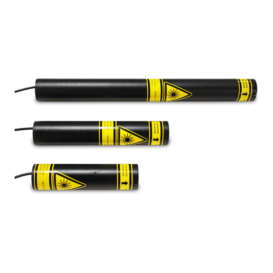
REO 32734 User And Operational Manual
Visible wavelength helium-neon laser system
Hide thumbs
Also See for 32734:
- User and operational manual (14 pages) ,
- User and operational manual (11 pages)
Table of Contents
Advertisement
VISIBLE WAVELENGTH
HELIUM-NEON LASER SYSTEM
USER'S GUIDE TO OPERATION
Research Electro-Optics, Inc.
5505 Airport Boulevard Boulder, Colorado 80301
Phone - (303) 938-1960 Fax - (303) 447-3279
_______________________________________________________________________________________________________________________________
Advertisement
Table of Contents

Summary of Contents for REO 32734
- Page 1 VISIBLE WAVELENGTH HELIUM-NEON LASER SYSTEM USER'S GUIDE TO OPERATION Research Electro-Optics, Inc. 5505 Airport Boulevard Boulder, Colorado 80301 Phone - (303) 938-1960 Fax - (303) 447-3279 _______________________________________________________________________________________________________________________________...
-
Page 2: Table Of Contents
REF-177 UNPACKING ................................. 3 SHIPPING INVENTORY ..............................3 SAFETY INFORMATION ..............................3 COMPLIANCE ................................5 1: L ......................... 6 IGURE ASER ABEL LACEMENT IAGRAM 2: P ......................6 IGURE OWER UPPLY ABEL LACEMENT IAGRAM OPERATING INSTRUCTIONS FOR POWER SUPPLIES ..................... 7 3: F .......................... -
Page 3: Unpacking
REF-177 UNPACKING • Inspect the packing container for any damage that may have occurred during shipment. • Contact the shipper immediately if the laser or power supply has been damaged during shipping. • Packing materials are specifically designed to protect against shipping damage. •... - Page 4 Recommended Eyewear Maximum Permissible Nominal Ocular Part Number Description Optical Density (OD) Exposure (MPE) W/cm2 Hazard Distance (NOHD) (m) 32734 LASER SYSTEM, 633nm, STBLZD, >1.5mW 0.28 0.0026 5.63 32172 LASER SYSTEM, 3.39µm, 2.0mW, POL 30990 LASER SYSTEM, 633nm, 5.0mW, RANDOM 0.74...
-
Page 5: Compliance
REF-177 • High voltage is present at all times when the key switch on the control box is in the “ON” position. • The power cord and plug are provided with a ground line. To avoid possible shock ensure that the plug is properly connected to a ground point at the electrical connection. - Page 6 REF-177 • Power • Date of Manufacture • Serial Number G. Power Supply Manufacturing Label Includes the Following: • Model Number • Serial Number • Input Power • Replacement Fuse Information Figure 1: Laser Head Label Placement Diagram Figure 2: Power Supply Label Placement Diagram...
-
Page 7: Operating Instructions For Power Supplies
REF-177 Research Electro-Optics (REO) certifies that our laser heads and lab power supplies meet the appropriate CE requirements. For the CE regulations to be met, all lab power supplies must be used with an input line cord with a length of less than 3 meters. - Page 8 REF-177 Figure 4: Back Panel of Power Supply Fuse Assembly/Power Cord Installation The power supply will not operate until the fuse assembly is correctly installed. The enclosed fuse assembly can be found with a 250V - 5A slow blow fuse installed. A component within this fuse assembly is the input line voltage selector.
- Page 9 REF-177 Once the fuse assembly and voltage selector are correctly installed, insert the supplied US IEC320 Female to Nema 5-15P power cord into the power supply unit. To ensure proper and optimal laser operation, only use the power supply that is appropriate for the HeNe laser head in use.
-
Page 10: Operating Instructions For Laser Head With Power Supply
REF-177 Figure 7: Two Position Shutter Assembly Maintenance & Service The power supply unit contains no user serviceable parts. Return the power supply unit to Newport for any service issues that may arise. OPERATING INSTRUCTIONS FOR LASER HEAD WITH POWER SUPPLY The cylindrical construction of the laser head allows for easy mounting in ring clamps, V-blocks, or similar mounting hardware without affecting the laser's alignment. -
Page 11: Product Warranty Statement
The foregoing warranty does not apply to Products or components thereof which are (a) repaired, modified or altered by any party other than REO; (b) used in conjunction with equipment not provided or authorized by REO; (c) subjected to unusual physical, thermal, electrical or optical stress, improper installation, misuse, abuse, tampering, accident, contamination, or negligence in use, storage, transportation or handling;... - Page 12 (equivalent to 3 inch thick high density foam on all sides) and insure that the power supply and tube are secured within the box so they do not move during shipment. REO will not assume responsibility for any shipping damages unless the laser is sent in REO-supplied packaging.
-
Page 13: Eu Declaration Of Conformity
REF-177 EU DECLARATION OF CONFORMITY CE Compliance refers to following model numbers: Part Number Description 32734 LASER SYSTEM, 633NM, STBLZD, >1.5MW 32172 LASER SYSTEM, 3.39UM, 2.0MW, POL 30990 LASER SYSTEM, 633NM, 5.0MW, RANDOM 30025 LASER SYSTEM, 633NM,1.5MW,POL, 9.5" 31007 LASER SYSTEM, 633NM, 0.8MW, POL 31008 LASER SYSTEM, 633NM, 0.5MW, RAN...


Need help?
Do you have a question about the 32734 and is the answer not in the manual?
Questions and answers