
Related Manuals for Alfa Laval ThinkTop v.3.0


Summary of Contents for Alfa Laval ThinkTop v.3.0
- Page 1 Instruction Manual ® ThinkTop AS-Interface v.2.1 (31 nodes) & v.3.0 (62 nodes) 29.5 - 31.6 VDC TD 800-242_1 Patented Sensor System Registered Design Registered Trademark ESE00356-EN12 2013-07 Original manual...
-
Page 3: Table Of Contents
Table of contents The information herein is correct at the time of issue but may be subject to change without prior notice 1. CE Declaration of Conformity ............... 2. Safety ....................2.1. Important information ................2.2. Warning signs ..................2.3. Safety precautions ................3. -
Page 4: Ce Declaration Of Conformity
- Low Voltage Directive (LVD) 2006/95/EF - EMC Directive 2004/108/EF - ROHS Directive 2002/95/EEC Manager, Product Centres, Compact Bjarne Søndergaard Heat Exchangers & Fluid Handling Title Name Alfa Laval Kolding Company Signature Designation... -
Page 5: Safety
2 Safety Unsafe practices and other important information are emphasized in this manual. Warnings are emphasized by means of special signs. All warnings in the manual are summarized on this page. Pay special attention to the instructions below so that severe personal injury or damage to the top unit are avoided. 2.1 Important information Always read the manual before using the top unit! WARNING... -
Page 6: Safety Precautions
2 Safety Unsafe practices and other important information are emphasized in this manual. Warnings are emphasized by means of special signs. All warnings in the manual are summarized on this page. Pay special attention to the instructions below so that severe personal injury or damage to the top unit are avoided. 2.3 Safety precautions Installation Always read the technical data thoroughly. -
Page 7: General Information
3 General information 3.1 AS-Interface in general The ThinkTop is designed to ensure optimum valve control in conjunction with Alfa Laval sanitary valves and it is compatible with all major PLC systems (Programmable Logic Controller with AS-interface). The ThinkTop can be equipped with 0-3 solenoid valves. The solenoids are electrically controlled by the AS-Interface and when activated the compressed air is activating the air actuator. -
Page 8: Technical Specifications
10. Terminals 20. External connections TD 800-267 TD 800-267 Type: Alfa Laval “No Touch” System. For wire connections: See 5.4 Electrical connection, internal“. F F eatures - Tolerance programmes. - Self adjustment programme (SRC/ARC valves only). - Built-in maintenance monitor. - Page 9 4 Technical specifications Self Adjustment (SRC/ARC valves only) The self adjustment feature is an exceptional aspect of the ThinkTop design. A programme can be activated to allow an adjustment of the tolerance band if the seals in the valve are being compressed or are worn. When the tolerance band of the unit has been adjusted 0.3 mm, an alert warning will appear in the form of a status signal and a flashing maintenance LED.
- Page 10 4 Technical specifications External sensors The external sensors are used for seat-lift supervision when seat-lift can not be internally detected. The sensors get their supply voltage from the terminal row. The output signals from the sensors are connected to two inputs on the terminal row on the internal sensor unit.
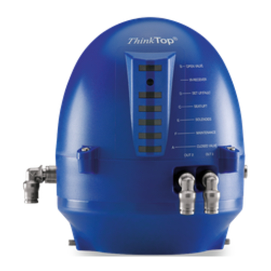
- Page 11 4 Technical specifications ThinkTop Visual Indications LED Indications “Open valve” (Yellow) LED B LED B IR-Receiver LED D “Setup/Internal fault” (Red) LED D LED C “Seat-lift 1/2” (Yellow) LED C LED E “Solenoid valves” (Green) LED E LED F “Maintenance” (Orange) LED F LED A LED A...
- Page 12 4 Technical specifications Technical specifications Up to 3 solenoid valves in each unit. Type 3/2 or 5/2 valve (only possible with one 5/2 valve). Air supply 300-900 kPa (3-9 bar). Filtered air, max. particles or dirt 5 μ 5-5 mg/m Max.
- Page 13 4 Technical specifications Micro environment demand specifications Temperature Working: -20°C to +85°C IEC 68-2-1/2 Storage: -40°C to +85°C IEC 68-2-1/2 Temperature change: -25°C to +70°C IEC 68-2-14 Vibration 10-55 Hz, 0.7 mm IEC 68-2-6 55-500 Hz, 10g 3 x 30 min, 1 octave/min Drop test IEC 68-2-32 Humidity...
-
Page 14: Installation
5 Installation 5.1 Installation on air actuators Step 1 Always read the technical data thoroughly. ® Always have the ThinkTop electrically connected by authorised personnel. Step 2 SRC/ARC only 1. Fit the air fittings on actuator if not mounted. 2. Fit the activator stem (magnet) and tighten c c arefully with a spanner. - Page 15 5 Installation Step 5 Fit the ø6 mm (1/4”) air tubes to ThinkTop. (see drawing “Air connections” page 18). S S tep 6 Fit the air tubes to the actuator (see drawing “Air connections” page 18). TD 800-131 S S tep 7 Untighten the four screws and pull off cover of ThinkTop.
- Page 16 5 Installation Step 9 Make sure the cable gland is completely tightened. TD 800-249 S S tep 10 Set up the ThinkTop (see chapter 6 Setup diagram). NOTE! The unit can be set up with the cover installed by using the IR keypad.
-
Page 17: Installation On Series 700 Valves
5 Installation 5.2 Installation on Series 700 valves Step 1 Installation on air actuators: 1. Remove the cover by loosening the four cover screws. 2. Separate the adapter from the base by loosening the three recess screws on top of the base. TD 800-250 S S tep 2 1. -
Page 18: Air Connections
5 Installation 5.3 Air connections TD 800-252 A. Air restriction (throttle function) air inlet/outlet B. Air out 1A C. Air exhaust D. Air out 1B (5/2 port solenoid valve only) E. Solenoid 3/2 or 5/2 F. 3/2 Solenoid valves only G. -
Page 19: Electrical Connection, Internal
5 Installation 5.4 Electrical connection, internal A Bus Connection C PWM Jumper* * *) B Internal connections to D Incoming signals from external sensors * * ***) solenoid 1-3 * * **) E Supply to external sensors * * ) 1 N/C ASI + ASI -... -
Page 20: Setup Diagram
6 Setup diagram ® 6.1 ThinkTop setup utilising IR keypad General Flashing LED means no value set. Steady LED means value set as shown. Default: Step 2, factory-set tolerance band +/- 5 mm Step 3-8, disabled D LED: Active during set-up: Flashing in step 1 Steady in all other steps Or during operations, error condition:... - Page 21 6 Setup diagram Enter Setup Step 1 – Save and Exit Exit no change accepted Next C step E S S tep 2 – Setup valve type Default SRC/ARC Unique Mixproof SMP-SC Unique 7000 +/- 5mm Series 700 (LKLA-T) SMP-SC SF SMP-BC Unique Mixproof PMO/Curd (O O nly used...
-
Page 22: Thinktop ® Setup Utilising Local 'I' And 'Ii' Keys
6 Setup diagram ® 6.2 ThinkTop setup utilising local ’I’ and ’II’ keys General Default is: Step 2, tolerance is +/- 5 mm Step 3-8, disabled Timeout: A 60 sec. timeout is started as soon as any button(s) is released. On timeout the setup is exited with no changes saved. - Page 23 6 Setup diagram Enter Setup Step 1 – Save and Exit NextC Exit no change accepted step E Step 2 – Setup valve type Unique Mixproof Unique 7000 Default SRC/ARC SMP-SC (LKLA-T) Unique Mixproof PMO/Curd +/- 5mm Series 700 SMP-SC SMP-BC (O O nly used SRC-PV...
-
Page 24: Thinktop ® Quick Setup Guide
6 Setup diagram ® 6.3 ThinkTop Quick setup guide Valve: Unique SSV, SRC/ARC type NC (selfadjustment disabled) - and wait until red LED flashes Push: Push: - hold for 5 sec (clear all stored parameters) Push: Push: (red + yellow LED) Push: (red + yellow + green LED) Push:... - Page 25 6 Setup diagram Valve: LKB Valve (Butterfly) NO - and wait until red LED flashes Push: Push: - hold for 5 sec (clear all stored parameters) Push: Push: (red + yellow LED) Push: (red + yellow + green LED) Push: - to approve valve closed (indication stem up) Activate - to approve valve closed...
-
Page 26: Troubleshooting
7 Troubleshooting 7.1 Troubleshooting and LEDs Below is stated the meaning of the LEDs’ indications for fault finding in connection with the operation of the ThinkTop. Red flashing: Unit in set-up mode or internal software fault. If internal software fault, re-programme unit. Red steady: Unit in set-up mode or internal hardware fault. - Page 27 7 Troubleshooting Yellow steady: Position B (open valve). Yellow B Yellow steady: Position C (Seat lift 1-2 or external sensors). Yellow C Green steady: Solenoid valves energized. Green Note! During set-up LED lights have different functions.
-
Page 28: Maintenance
8 Maintenance Study the instructions carefully. Handle scrap correctly. Always keep spare X-rings in stock. ® 8.1 Dismantling the ThinkTop Step 1 1. Untighten the two Allen screws and remove the ThinkTop from the actuator. 2. Pull out X-ring (19) and replace it. S S tep 2 1. - Page 29 8 Maintenance Study the instructions carefully. Handle scrap correctly. Always keep spare X-rings in stock. Step 5 To remove the sensor unit untighten screw and pull out the sensor unit. TD 800-256...
-
Page 30: Assembling The Thinktop
8 Maintenance Study the instructions carefully. Handle scrap correctly. Always keep spare X-rings in stock. ® 8.2 Assembling the ThinkTop Step 1 Place sensor unit in base and tighten screw (torque: 1 Nm). TD 800-257 S S tep 2 1. Replace the black X-ring. 2. - Page 31 8 Maintenance Study the instructions carefully. Handle scrap correctly. Always keep spare X-rings in stock. Step 5 1. Replace the black X-ring. 2. Mount ThinkTop on actuator.
-
Page 32: Dismantling And Assembly Of Series 700 Valves
8 Maintenance Study the instructions carefully. Handle scrap correctly. Always keep spare X-rings in stock. 8.3 Dismantling and assembly of Series 700 valves Step 1 Installation on air actuators: 1. Remove the cover by loosening the four cover screws. 2. Separate the adapter from the base by loosening the three recess screws on top of the base. -
Page 33: Parts List And Service Kits
9 Parts list and Service Kits The drawings show ThinkTop AS-Interface v.2.1 (31 nodes) & v.3.0 (62 nodes) 29.5 - 31.6 VDC. The items refer to the parts lists in the following sections 9.1 Drawings for ThinkTop AS-Interface TD 800-263 TD 800-149 ø137 mm Note! This is the basic design. -
Page 34: Thinktop As-Interface
9 Parts list and Service Kits The drawings show ThinkTop AS-Interface v.2.1 (31 nodes) & v.3.0 (62 nodes) 29.5 - 31.6 VDC. The items refer to the parts lists in the following sections 9.2 ThinkTop AS-Interface TD 800-270... - Page 35 9 Parts list and Service Kits The drawings show ThinkTop AS-Interface v.2.1 (31 nodes) & v.3.0 (62 nodes) 29.5 - 31.6 VDC. The items refer to the parts lists in the following sections Parts list Pos. Denomination Shell complete Screw Washer Sensor board Solenoid valve...
-
Page 37: Drawings For Thinktop As-Interface For Series 700
9 Parts list and Service Kits The drawings show ThinkTop AS-Interface v.2.1 (31 nodes) & v.3.0 (62 nodes) 29.5 - 31.6 VDC Series 700 valves. The items refer to the parts lists in the following sections 9.3 Drawings for ThinkTop AS-Interface for Series 700 TD 800-269 TD 800-205 ø137 mm... -
Page 38: Thinktop As-Interface For Series 700
9 Parts list and Service Kits The drawings show ThinkTop AS-Interface v.2.1 (31 nodes) & v.3.0 (62 nodes) 29.5 - 31.6 VDC Series 700 valves. The items refer to the parts lists in the following sections 9.4 ThinkTop AS-Interface for series 700... - Page 39 9 Parts list and Service Kits The drawings show ThinkTop AS-Interface v.2.1 (31 nodes) & v.3.0 (62 nodes) 29.5 - 31.6 VDC Series 700 valves. The items refer to the parts lists in the following sections Parts list Pos. Denomination (Pos.9,12,13,14 included) Shell complete Screw...
- Page 40 © Alfa Laval Corporate AB This document and its contents is owned by Alfa Laval Corporate AB and protected by laws governing intellectual property and thereto related rights. It is the responsibility of the user of this document to comply with all applicable intellectual property laws. Without limiting any rights related to this document, no part of this document may be copied, reproduced or transmitted in any form or by any means (electronic, mechanical, photocopying, recording, or otherwise), or for any purpose, without the expressed permission of Alfa Laval Corporate AB.
Need help?
Do you have a question about the ThinkTop v.3.0 and is the answer not in the manual?
Questions and answers