
Related Manuals for Alfa Laval ThinkTop V55


Summary of Contents for Alfa Laval ThinkTop V55
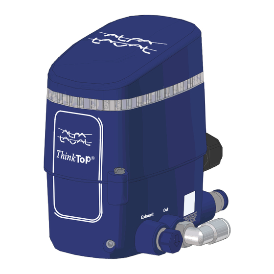
- Page 1 Alfa Laval ThinkTop® V55 Sensing and control 2069-0000 Instruction Manual Lit. Code 200013632-1-EN-GB BRITISH ENGLISH...
- Page 2 © Alfa Laval AB 2024-10 This document and its contents are subject to copyrights and other intellectual property rights owned by Alfa Laval AB (publ) or any of its affiliates (jointly “Alfa Laval”). No part of this document may be copied, re-produced or transmitted in any form or by any means, or for any purpose, without Alfa Laval’s prior express written permission. Information and services provided in this document are made as a benefit and service to the user, and no representations or warranties are made about the accuracy or suitability of this information and these services for any purpose.
-
Page 3: Table Of Contents
Contents 1 Declaration of Conformity ................... 5 EU Declaration of Conformity..................5 UK Declaration of Conformity..................6 2 Safety ..........................7 Safety Signs......................8 Safety Precautions....................9 Warning Signs in Text....................10 Requirements of Personnel..................11 Recycling Information....................12 3 Introduction .........................13 About ThinkTop......................13 About this manual....................13 4 Installation... - Page 4 Ordering Spare Parts....................35 Alfa Laval Service....................35 Warranty - definition....................36 9 Parts List and Exploded View ................ 37 ThinkTop V55......................37...
-
Page 5: Declaration Of Conformity
1 Declaration of Conformity 1.1 EU Declaration of Conformity The designated company Alfa Laval Kolding A/S, Albuen 31, DK-6000 Kolding, Denmark, +45 79 32 22 00 Company name, address and phone number Hereby declare that Top Unit for Valve Control and Indication Designation ThinkTop®... -
Page 6: Declaration Of Conformity
1 Declaration of Conformity 1.2 UK Declaration of Conformity The designated company Alfa Laval Kolding A/S, Albuen 31, DK-6000 Kolding, Denmark, +45 79 32 22 00 Company name, address and phone number Hereby declare that Top Unit for Valve Control and Indication Designation ThinkTop®... -
Page 7: Safety
Instruction Manual without prior notice or any obligation. The English version of the Instruction Manual is the original manual. Alfa Laval cannot be held responsible for incorrect translations. In case of doubt, the English version applies. -
Page 8: Safety Signs
2 Safety 2.1 Safety Signs Warning Signs General warning. Electricity. Corrosive substance. 200013632-1-EN-GB... -
Page 9: Safety Precautions
2.2 Safety Precautions All warnings in the manual are summarised on this page. Pay special attention to the instructions below so that severe personal injury and/or damage to the supplied Alfa Laval product is avoided. Installation Always read the technical data thoroughly... -
Page 10: Warning Signs In Text
Indicates a potentially hazardous situation which, if not avoided, could result in death or serious injury. CAUTION Indicates a potentially hazardous situation which, if not avoided, may result in minor or moderate damage to the supplied Alfa Laval product. NOTE Indicates important information to simplify or clarify procedures. 200013632-1-EN-GB... -
Page 11: Requirements Of Personnel
Trainees can perform tasks under the supervision of an experienced employee. People in general The public shall not have access to the supplied Alfa Laval product. In some cases, specially skilled personnel may need to be hired (i.e. electricians, welders). In some cases the personnel has to be certified according to local regulations with experience of similar types of work. -
Page 12: Recycling Information
Metal straps should be sent for material recycling Maintenance During maintenance, oil (if used) and wear parts in the supplied Alfa Laval product should be replaced. • Oil and all non-metal wear parts must be disposed of in accordance with local regulations •... -
Page 13: Introduction
V55 series The ThinkTop V55 features a compact housing with the same functionality as the ThinkTop V50. The product fits the SS/SL actuator of all sizes of the Unique DV-ST Ultrapure diaphragm valves. - Page 14 This page is intentionally left blank.
-
Page 15: Installation
4 Installation 4.1 Tools To carry out the installation, you need the following tools: Tool Size Example Hex key 2,5 mm 2069-0021 Adjustable spanner or flat wrenches 7, 14, 19 mm 2069-0022 Phillips screwdriver Phillips 2 2069-0023 Flat spanner (max thickness of 9 mm) 27 mm 2069-0024 Adjustable pin wrench... -
Page 16: Mechanical Installation
4 Installation 4.2 Mechanical Installation Mechanical installation is a three-step process where you mount the adapter to the valve top, the sensor target to the actuator stem, and the ThinkTop on the adapter. Fit the black adaptor to the valve. (Remove the mechanical indication first, if present) Tighten the adapter using a 27 mm spanner... - Page 17 Installation 4 Mount the ThinkTop centred and flat against the adaptor while tightening the set screws. Use a 2.5 mm hex key to lightly tighten one of the two set screws. Tighten the second set screw (1...1.5 Nm). Tighten the first set screw (1...1.5 Nm) 2069-0006 200013632-1-EN-GB...
-
Page 18: Pneumatic Installation
4 Installation 4.3 Pneumatic Installation Before you begin the pneumatic installation, cut the hoses to the preferred length. Connect the air hoses between the air connectors on the ThinkTop and the air ports on the valve. Connect the supply air hose to the Air in connector and turn on the supply air. -
Page 19: Electrical Installation, Digital-Io 24V
Installation 4 4.4 Electrical Installation, Digital-IO 24V a) Loosen screws using Phillips 2 screwdriver. b) Lift cover upwards to remove it from the base. c) Install the cable and tighten the cable gland using a 19 mm wrench. (3 Nm). Or tighten the M12 connector using a 14 mm Wrench. -
Page 20: Electrical Installation, As-Interface
4 Installation 4.5 Electrical Installation, AS-interface a) Loosen screws using Phillips 2 screwdriver. b) Lift cover upwards to remove it from the base. c) To allocate an address, use your preferred addressing device. See the device manual for more information. d) Install the cable and tighten the cable gland using a 19 mm wrench. -
Page 21: Electrical Installation, Io-Link
Installation 4 4.6 Electrical Installation, IO-link a) Loosen screws using a Phillips 2 screwdriver. b) Lift cover upwards to remove it from the base. c) Install the cable and tighten the M12 connector using a 14 mm wrench (0.6… 1.5 Nm). d) Put the top cover back in place and tighten screws (0.5...1 Nm). -
Page 22: Adapter Kit Installation
4 Installation 4.7 Adapter Kit Installation Mount the sensor target adapter to the actuator stem 1..1.5 Nm. An 11 mm key can be used for tightening. NOTE The adapter kit is compatible with the Small single seat valve and the Vacuum breaker valve. -
Page 23: Setup
5 Setup 5.1 Auto Setup Auto Setup activates all relevant solenoid valves and automatically completes the setup. Perform Auto Setup Remove the top cover by turning it anticlockwise and then lifting it upwards. Press the SELECT button and then the ENTER button to initiate the Auto Setup functionality. -
Page 24: Flex Setup
• Each step is keyed to specific visual feedback • The ThinkTop V55 has two setup steps • All steps are generic and the labels that are used are only placeholders • There is a 5 minute timeout in each setup. On timeout, the setup is cancelled, and no changes are saved The valve can be manually controlled conveniently via the solenoid valves. -
Page 25: Perform Flex Setup
Setup 5 5.2.1 Perform Flex Setup Remove the top cover. Press the SELECT button two times to navigate to the Seat valve option, then press ENTER. Store the valve positions. Green flashing [De-energized position] Position the valve in de-energized position. Press ENTER to store. -
Page 26: Live Setup
5 Setup 5.3 Live Setup Live Setup is especially suited for live commissioning and live replacement. Unlike Auto Setup, Live Setup does not automatically activate the solenoid valves. It waits for all the detected solenoid valves to be energized by the PLC, and then saves the related positions detected by the sensor system. -
Page 27: Options
Setup 5 5.4 Options The operational functionality of the ThinkTop can be further customized with the following options. Key lock If you want to tamper proof the control board, the SELECT button can be locked by holding the ENTER button for 7s until the 4 first LED’s in the array has come ON. - Page 28 This page is intentionally left blank.
-
Page 29: Troubleshooting
6 Troubleshooting 6.1 Calculating the Error Code You need the error code to use the troubleshooting table. To determine the error code, you add the numbers to the right of the active LED’s. Example: The following control board shows 1 + 4 + 16, which results in error code #21. -
Page 30: Error Descriptions
6 Troubleshooting 6.2 Error Descriptions Error description Troubleshooting advice Key lock active The SELECT button is locked. It can be unlocked by holding the ENTER button for 7s until the 4 first LEDs has come ON. Sensor target missing Verify that the sensor target is installed correctly. Position not reached During operation, the sensor target or the seat lift sensor did not reach the intended posi- tion on time. - Page 31 Troubleshooting 6 Error description Troubleshooting advice Safety stop The sensor target has moved past the max. limit. The unit is locked in fail safe mode to protect the housing. • Verify that the actuator stroke length is compatible with the control unit The condition is reset on re-power.
-
Page 32: Interpreting The Error Code Patterns
6 Troubleshooting 6.3 Interpreting the Error Code Patterns You can identify an error code by looking at the LED colour pattern. The pattern is displayed in the following table: Auto Flex Seat valve Rotary valve Error 16 17 18 19 20 21 22 23 24 25 26 27 28 29 30 31 2066-0063 Example: Auto... -
Page 33: Technical Data
7 Technical Data NOTE Technical data must be observed during installation, operation and maintenance. All personnel should be informed about the technical data. 7.1 Technical Data Material Plastic parts Nylon PA 12 Steel parts 1.4301 / 304 Gaskets Nitril / NBR Air fittings Nickel plated / Nylon PA6 M12 chassis connector... -
Page 34: Operational Data
7 Technical Data Cable connection Main cable gland entry Digital M16 (ø4 - ø10 mm²) (0.16" - 0.39") Main cable gland entry AS-I M16 (ø2 - ø7 mm²) (0.08" - 0.28") Max wire diameter 0.75 mm² (AWG20) M12 chassis connector AS-Interface V55 2 wire, 4-pin series IO-Link interface V55... -
Page 35: Spare Parts
Alfa Laval representative for availability. You can find our spare part catalogue at https://hygienicfluidhandling-catalogue.alfalaval.com. Always use Alfa Laval genuine spare parts. The warranty of Alfa Laval products is dependent on use of Alfa Laval genuine spare parts. 8.1 Ordering Spare Parts When ordering spare parts, please always state: 1. -
Page 36: Warranty - Definition
8.3 Warranty - definition WARNING The rules of Intended use are absolute. Use of the supplied Alfa Laval product is allowed only when in compliance with the technical data supplied with the Intended use. Differing utilisation, other than agreed with Alfa Laval Kolding A/S, exclude any liability and warranty. -
Page 37: Parts List And Exploded View
9 Parts List and Exploded View 9.1 ThinkTop V55 Pos. Qty. Denomination Pos. Qty. Denomination Top cover, complete 10.2 Air fitting, straight, 1/4 inch Base seal 12.1 Air fitting angle, 6mm Screw Torx 10 12.2 Air fitting, anglet, 1/4 inch...
Need help?
Do you have a question about the ThinkTop V55 and is the answer not in the manual?
Questions and answers