
Related Manuals for Alfa Laval ThinkTop Basic Digital 10


Summary of Contents for Alfa Laval ThinkTop Basic Digital 10
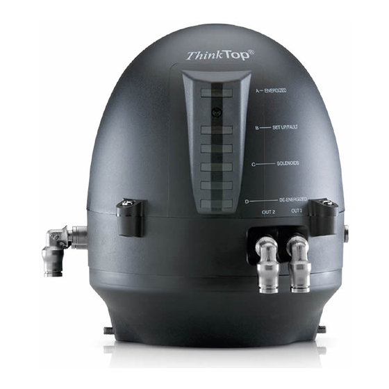
- Page 1 Instruction Manual ThinkTop Basic Digital 10 - 30 VDC PNP/NPN ® ESE00225EN1 2006-11...
- Page 3 Type Year is in conformity with the following directives with amendments: Low Voltage Directive 73/23/EEC EMC Directive 89/336/EEC ROHS Directive 2002/95/EC Manager, Product Centres, Compact Heat Exchangers & Fluid Handling Bjarne Søndergaard Title Name Alfa Laval Kolding Company Signature Designation...
-
Page 5: Table Of Contents
Table of contents The information contained herein is correct at the time of issue but may be subject to change without prior notice. 1. Safety ....................6 1.1 Important information ............... 6 1.2 Warning signs................... 6 1.3 Safety precautions................6 2. -
Page 6: Safety
1.1 Important information 1. Safety 1.2 Warning signs 1.3 Safety precautions Unsafe practices and other important information are emphasized in this manual. Warnings are emphasized by means of special signs. All warnings in the manual are summarized on this page. Pay special attention to the instructions below so that severe personal injury or damage to the top unit are avoided. -
Page 7: General Information
2. General information 2.1 Digital in general The ThinkTop Basic is designed to ensure optimum valve control in conjunction with Alfa Laval valves and it is compatible ® with most PLC systems (Programmable Logic Controllers maker with PNP/NPN interface). The ThinkTop Basic can be equipped with 0-3 solenoid valves. -
Page 8: Technical Specifications
® 3.1 “No Touch” sensor system PLC, DC feedback Type: Alfa Laval “No Touch” System For wire connections: See section 4.5 “Electrical connection, internal”. Features • Easy and simple set-up, using locally pushbuttons • No manual sensor adjustments at all •... - Page 9 3.1 ThinkTop 3. Technical specifications Basic, PLC 8-30 VDC interface ® The fulfilling of the UL requirements in UL 508 requires that the unit is supplied by an isolating source complying with the requirements for class 2 power units (UL 1310) or class 2 and 3 transformers (UL 1585). Sensor detection system: Sensor accuracy: +/- 0,1 mm.
- Page 10 3.1 ThinkTop 3. Technical specifications Basic, PLC 8-30 VDC interface ® Solenoid Valves: 0 to 3 solenoid valves in each unit possible. Type: 3/2 or 5/2 port (only possible with one 5/2 port). Air supply: 300-900 kPa (3-9 bar). Filtered air, max. particles or dirt: 0.01 mm.
-
Page 11: Installation
4.1 Installation on air actuators 4. Installation Step 1 Always read the technical specifications thoroughly (see chapter 3). Always have the ThinkTop Basic electrically connected by authorized personnel. ® Always install the ThinkTop Basic before valve or relay is in a safe position. ®... - Page 12 4. Installation 4.1 Installation on air actuators Step 5 Fit the ø6 mm (1/4”) air tubes to ThinkTop Basic. ® (see drawing “Air connections” later in this chapter). Step 6 Fit the air tubes to the actuator (see drawing “Air connections” later in this chapter). Step 7 Untighten the four screws and pull off cover of ThinkTop ®...
- Page 13 4.1 Installation on air actuators 4. Installation Step 9 Make sure the cable gland is completely tightened. Step 10 Set up the ThinkTop Basic (see chapter 5). ® NOTE! The unit can be set up with the cover installed by using the IR keypad. To energize the valve, use a separate air tube or be in radio contact with the control room.
-
Page 14: Installation On Series 700 Valves
4. Installation 4.2 Installation on Series 700 valves Step 1 Installation on 1. Remove the cover by loosening the four cross recess air actuators: screws. 2. Separate the adapter from the base by loosening the three recess screws on top of the base. Step 2 1. -
Page 15: Air Connections
4.3 Air connections 4. Installation Air out 1A Air exhaust Manual hold override Air out 1B (5/2 port solenoid valve only) Solenoid valve Air out 2 Air out 3 Air in... -
Page 16: Electrical Connection
4.4 Electrical connection 4. Installation Electrical connections De-energized (PLC input) Energized (PLC input) Activation of solenoid # 1 (PLC output) Activation of solenoid # 2 (PLC output) Activation of solenoid # 3 (PLC output) Supply voltage sensor (+) 10-30 VDC Supply voltage sensor (0) 0 V Common supply solenoids PNP/NPN jumper*) -
Page 17: Setup Diagram
5.1 ThinkTop Basic, setup 5. Setup diagram ® Timeout: A 30 second time-out is started as soon as any button(s) are released. If no button is pressed during the time-out period, go to normal condition (cancel & exit). “red” steady “red”... -
Page 18: Maintenance
6.1 Dismantling of ThinkTop Basic 6. Maintenance ® Study the instructions carefully. Handle scrap correctly. Always keep spare X-rings in stock. Step 1 1. Remove the ThinkTop Basic from the actuator. ® 2. Pull out X-ring (19) and replace it. Step 2 1. - Page 19 6.1 Dismantling of ThinkTop 6. Maintenance Basic ® Study the instructions carefully. Handle scrap correctly. Always keep spare X-rings in stock. Step 5 To remove the sensor unit untighten screw and pull out the sensor unit.
-
Page 20: Assembly Of Thinktop ® Basic
6.2 Assembly of ThinkTop Basic 6. Maintenance ® Study the instructions carefully. Handle scrap correctly. Always keep spare X-rings in stock. Step 1 Place sensor unit in base and tighten screw (torque: 1 Nm). Step 2 1. Assemble base with adapter by turning adapter slightly anticlockwise and tighten the three screws (1.9 Nm).
Need help?
Do you have a question about the ThinkTop Basic Digital 10 and is the answer not in the manual?
Questions and answers