Table of Contents
Advertisement
Quick Links
Advertisement
Table of Contents

Related Manuals for Intermec MaxiScan 1000


Summary of Contents for Intermec MaxiScan 1000
- Page 1 Integration Guide Manual P/N 3-380049-01 MaxiScan 1000 CCD Scan Engine...
- Page 2 The information contained in this document is for informational purposes only and is subject to change without notice. No part of this document may be copied or reproduced in any manner without the prior written permission of Intermec Technologies Corporation.
-
Page 3: Table Of Contents
Optional adaptor cable PC connection example External buzzer connection External LED connection Input / output synchronization 4 Technical characteristics ..........17 Data Reading distance Accessories 5 Setup..................20 Online setup with EasySet Slave mode Basic setup MaxiScan 1000 - Integration Guide... - Page 4 MaxiScan 1000 - Integration Guide...
-
Page 5: Before You Start
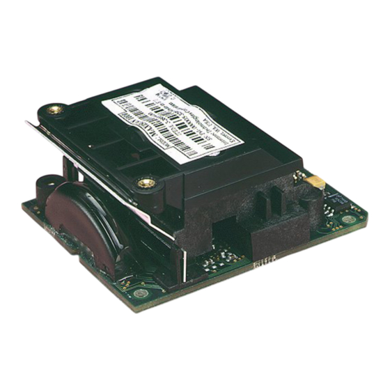
Before you start Introduction The MaxiScan 1000 (M1000) is a CCD scanning and decoding engine designed for integration into an OEM device. It is suitable for a wide range of retail and industrial applications. This Integration Guide explains how to install and set up your M1000. -
Page 6: Integration Considerations
An external input synchronization device can be used to activate the M1000 • The M1000 can send a synchronization output to control external devices according to the read result • See the Input/output synchronization section MaxiScan 1000 - Integration Guide... -
Page 7: Location And Reading Position
Pitch • Reduces bar width and is much more critical for high-density barcodes • Reading may be possible with a pitch angle up to 70° • Reduce pitch to increase reading efficiency pitch MaxiScan 1000 - Integration Guide... - Page 8 Reduces bar height • Reading may be possible with a skew angle up to 65° • Reduce skew to increase reading efficiency • A small skew angle (2-3° minimum) is good as it prevents specular reflection skew MaxiScan 1000 - Integration Guide...
-
Page 9: Installation
Installation Fixing in position ∅ = 2 mm plastic MaxiScan 1000 - Integration Guide... -
Page 10: Dimensions
2 Installation Dimensions 4.7 cm (1.85") 4.2 cm (1.65") 0.35 cm (0.14") 0.25 cm (0.1") 4.8 cm (1.89") 0.35 cm (0.14") 5.65 cm (2.22") 2.73 cm (1.07") 1.66 cm (0.65") 4.7 cm (1.85") MaxiScan 1000 - Integration Guide... -
Page 11: Mounting A Window
An anti-reflection coating increases performance (and permits a lower window angle) • Recommended maximum wavefront distortion = 0.2 wavelengths (peak to valley) over any 2.5 mm diameter area of the window • A scratched window reduces performance ± 30° MaxiScan 1000 - Integration Guide... -
Page 12: Connections
RTS* good read LED (external) buzzer (external) CTS* sync in reserved for download sync out reserved for download reserved reserved version RS-232 C (P/N 3-380012-00) level -8V/+8V version RS-232 TTL (P/N 3-380014-00) level 0V/+5V MaxiScan 1000 - Integration Guide... -
Page 13: Optional Adaptor Cable
7 RTS (PC output) 4 RTS (PC output) 10 buzzer (external) buzzer in cable housing 11 reserved for download 8 reserved for download 12 sync in 13 reserved for download 9 reserved for download 14 sync out MaxiScan 1000 - Integration Guide... -
Page 14: External Buzzer Connection
470 nF (30 mA max) MaxiScan + 5V External LED connection The good read LED can be deactivated from EasySet. pin 8 + 5V Ω LED (20 mA max) MaxiScan MaxiScan 1000 - Integration Guide... -
Page 15: Input / Output Synchronization
The M1000 sends a specified character when it performs a good read or does not perform a good read during an input synchronization cycle (according to setup). This software output can be combined with an action voltage level (high) or voltage level (low). MaxiScan 1000 - Integration Guide... - Page 16 Input synchronization: triggering by an opto-coupled cell +5 V +5 V Ω 4.7 k Ω 10 k pin 12 pin 2 Photelectric sensor M1000 Output synchronization: 30 mA max pin 14 Ω 4.7 k – pin 2 Conveyor command M1000 block MaxiScan 1000 - Integration Guide...
-
Page 17: Technical Characteristics
4000 lux Electrostatic discharge Depends on mounting and enclosure Shock resistance Depends on mounting and enclosure Sealing (dust etc.) Depends on mounting and enclosure > 50 000 hours MTBF User interface Depends on user setup MaxiScan 1000 - Integration Guide... -
Page 18: Reading Distance
0.1 mm (4 mil) 1.6" 1.2" 0.8" This chart shows the horizontal reading range for 90% contrast Code 39 barcodes read in the dark. 0.4" The reading distance is measured from the edge of the electronic board. 0" MaxiScan 1000 - Integration Guide... -
Page 19: Accessories
(compatible with RS-232 C cable). This cable includes a buzzer RS-232 C cable (compatible with RS-232 TTL adaptor 0-234032-00 cable and TTL version of M1000 TTL P/N 3-380014-00) Power supply 0-302029-01 Europe (except UK) 0-301029-01 0-303029-01 MaxiScan 1000 - Integration Guide... -
Page 20: Setup
Slave mode section). To set up your M1000 in a test configuration without using EasySet, scan the bar codes in the Basic setup section. The basic setup does not include all the configuration possibilities of the M1000. MaxiScan 1000 - Integration Guide... -
Page 21: Online Setup With Easyset
Set the COM port parameters to 19200 baud, 8 data bits, no parity Refer to the EasySet online help for a detailed explanation of how to use the EasySet System configuration software (including how to perform offline setup with barcodes printed from EasySet). MaxiScan 1000 - Integration Guide... -
Page 22: Slave Mode
In our example, the M1000 must receive the hexadecimal value 41 or its equivalent (ASCII character "A" for example), not the decimal value "41". To save the new configuration, send the "update current configuration" command to the M1000 (0x68 0x46 0x41 0x02 0x60 0x4C 0x6A). MaxiScan 1000 - Integration Guide... - Page 23 (9600, 7, E, 2) – interface n° 109 \41\4A\01\2D\60 Send the commands in ASCII format from the host terminal to the M1000. To save the new configuration, send the "update current configuration" command to the M1000 (\46\41\02\60). MaxiScan 1000 - Integration Guide...
- Page 24 The M1000 reads a bar code correctly and transmits the data, but the bar code reference does not exist in your database. Use the slave mode beep command to send 3 "error" beeps to the M1000. MaxiScan 1000 - Integration Guide...
-
Page 25: Basic Setup
Basic setup does not include all the configuration possibilities of the M1000. For a complete setup, use the EasySet System configuration software (see the Online setup with EasySet section). Plug in power supply System power ON Reset factory defaults (optional) \46\42\60 MaxiScan 1000 - Integration Guide... - Page 26 5 Setup Select baud rate (*) = default value 1200 \41\04\60 2400 \41\05\60 4800 \41\06\60 9600 (*) \41\07\60 19200 \41\08\60 38400 \41\09\60 Select data bits 7 (*) \42\60 \43\60 MaxiScan 1000 - Integration Guide...
- Page 27 5 Setup Select parity even (*) \46\01\60 \46\02\60 none \46\00\60 Select stop bits \44\60 2 (*) \45\60 Select postamble none \45\54\3E\00\60 Carriage Return + Line Feed (*) \45\54\3E\0D\3E\0A\60 MaxiScan 1000 - Integration Guide...
- Page 28 Code 128 / EAN 128 \41\5A\60 Interleaved 2 of 5 (minimum length=6) \41\4E\60 Standard 2 of 5 (minimum length=6) \41\50\60 UPC-A, UPC-E, EAN-8, EAN-13 (*) (UPC-A EAN-13) UPC-A, UPC-E, EAN-8, EAN-13 (UPC-A UPC-A) PDF417 (option) MaxiScan 1000 - Integration Guide...
- Page 29 Code 39 CODE 39 Code 128 CODE 128 Interleaved 2 of 5 12345678901234 Standard 2 of 5 123456 EAN-13 1234567890128 UPC-A 0 1 2 3 4 5 0 0 0 0 PDF417 Intermec Technologies Corporation PDF417 MaxiScan 1000 - Integration Guide...
Need help?
Do you have a question about the MaxiScan 1000 and is the answer not in the manual?
Questions and answers