Table of Contents
Advertisement
Quick Links
Advertisement
Table of Contents

Subscribe to Our Youtube Channel
Related Manuals for Maruyama MD300


Summary of Contents for Maruyama MD300
- Page 1 MD300 Owner's Manual...
- Page 2 Maruyama Mfg. Co., Inc. is liable for damages to other engine components caused by the failure of a warranted part still under warranty. The purchaser is responsible for the performance of the required maintenance, as defined by Maruyama Mfg.
- Page 3 MANUFACTURER'S WARRANTY COVERAGE: The 1995 and later model year small off-road engines are warranted for five years. If any emission- related part on your engine is defective, the part will be repaired or replaced by Maruyama U.S., Inc. free of charge.
- Page 4 Maruyama U.S., Inc. recommends that you retain all receipts covering maintenance on your small off-road engine, but Maruyama U.S., Inc. cannot deny warranty solely for the lack of receipts or for your failure to ensure the performance of all scheduled maintenance. Any replacement part or service that is equivalent in performance and durability may be used in non-warranty maintenance or repairs, and shall not reduce the warranty obligations of the engine manufacturer.
- Page 5 Maruyama U.S., Inc. recommends that you retain all receipts covering maintenance on your small off-road engine, but Maruyama U.S., Inc. cannot deny warranty solely for the lack of receipts or for your failure to ensure the performance of all scheduled maintenance...
-
Page 6: Table Of Contents
Important safety instructions will be identified by the following safety symbol: Operating instructions …………………… 4 Failure to comply with the instructions in this manual may result in serious injury or death. Maintenance ……………………………… 8 For additional assistance, contact any local authorized Maruyama dealer. Storage ……………………………………10 WARNING Warning label General Read operation manual thoroughly. -
Page 7: Accessories
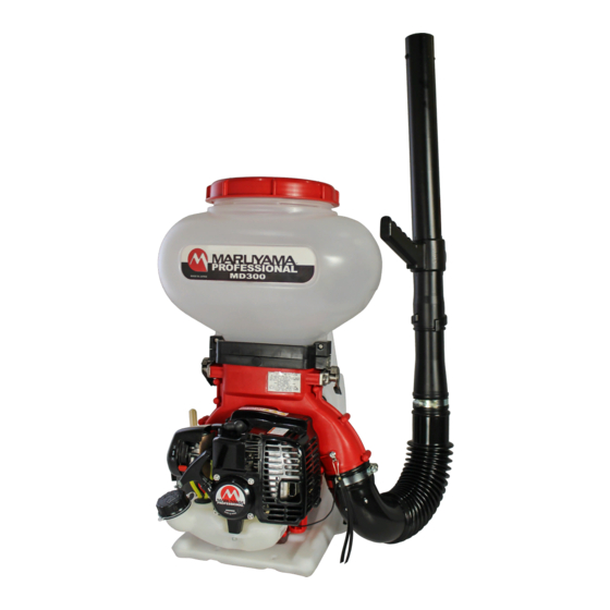
ACCESSORIES Band large Handle Operator's Manual Band small Box spanner swivel pipe Straight pipe Flexible pipe NAME OF EACH PART Ground braiding line, (Do not fix with tape, etc.) Chemical tank cover Chemical tank Engine Lock Lever Blower Band, small Band, large Fuel tank cap Straight pipe... -
Page 8: Before Operation
Throttle Lever Close The lowest step is the stop position. The throttle-lever adjusts the engine speed. High speed is obtained by moving the lever up. Throttle lever Shutter Lever Shutter lever The shutter lever adjusts the machine discharge quantity. The discharge quantity can be increased or decreased by moving the lever to your side while Powder chemical 多... -
Page 9: Operating Instructions
Setting Shutter “O” Shutter lever position is “中” Set connecting rod into setting and tighten lock nut. Adjust as necessary. Secure connecting rod assembly with R-pin. CAUTION When connecting Rod is set to link arm. Link arm must be turned right full. Shutter lever Link arm R-pin... - Page 10 Supply the Chemical 1. Align the shutter lever with “0”. 2. Remove the lump and feed in the chemical being careful not to spill it on the outside. When pouring the chemical into the tank, be careful not to spill the chemical on Close the outside.
- Page 11 Finishing Spray Push down the shutter lever and finish spraying. Push and contract the grip of the shutter lever. Stopping the Engine Pushdown the shutter-lever to the lowest stage and stop spraying. Move the throttle to the lowest stage keeping the shutter closed and then stop the engine. Lowest stage of the shutter ①Down Close...
- Page 12 Accurate Discharge Calculation Method ◦ The discharge may differ according to the relative humidity, type of chemical, etc. Use the graph and table as a guideline. ◦Accurate discharge can be obtained as follows. Set the intermediate rod in the shutter arm according to the type of the chemical to be sprayed. Perform a test spray by setting to the planned shutter opening.
-
Page 13: Maintenance
Note: The service intervals indicated are to be used as a guide. Service to be performed more frequently as necessary by operating condition. M : Service to be performed by an authorized Maruyama engine dealer. ★: Service more frequently under dusty conditions. - Page 14 Always replace a defective fuel filter. GENERAL CLEANING AND TIGHTENING The MARUYAMA duster will provide maximum performance for many hours, if it is maintained properly. Good maintenance includes regular checking of all fasteners for correct tightness, and cleaning the entire machine. Contact an authorized MARUYAMA dealer for additional maintenance suggestions.
-
Page 15: Storage
STORAGE For long-term storage of the duster, first perform all regular maintenance procedures and needed repairs. Empty the fuel tank. Disconnect the fuel supply line from the carburetor and depress the primer bulb until fuel stops discharging from the fuel-return line. Start the engine and allow it to run until it stops. - Page 16 Maruyama U.S., Inc. 4770 Mercantile Drive, suite 100, Fort Worth, TX 76137 U.S.A Phone 940-383-7400 Fax 940-383-7466 www.maruyama-us.com P/N. 277162-00 16.01 TAP/Q...
Need help?
Do you have a question about the MD300 and is the answer not in the manual?
Questions and answers