Table of Contents
Advertisement
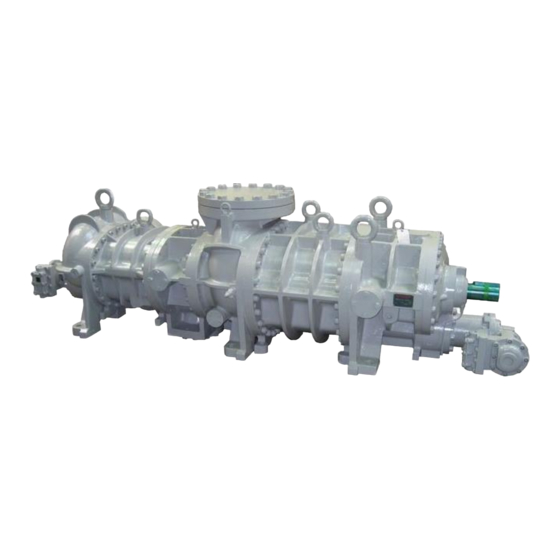
Compound 2-stage Screw Compressor
3225
C Instruction Manual
* *
3225LLLC/3225LLMC/3225LLSC/3225LLC/3225LMC/3225LSC
3225MLC/3225MMC/3225MSC/3225SLC/3225SMC/3225SSC
Before operating, servicing, or inspecting this product, read this manual thoroughly to fully
understand the contents.
Keep this Instruction Manual in a safe, designated place for future reference whenever the
manual is needed.
Specifications of this product and contents of this manual are subject to change without
prior notice due to technical improvements, and the like.
CAUTION
2202MYJE-MY-C8-N_2018.02.
Advertisement
Table of Contents

Related Manuals for mycom 3225**C Series

Summary of Contents for mycom 3225**C Series
- Page 1 2202MYJE-MY-C8-N_2018.02. Compound 2-stage Screw Compressor 3225 C Instruction Manual 3225LLLC/3225LLMC/3225LLSC/3225LLC/3225LMC/3225LSC 3225MLC/3225MMC/3225MSC/3225SLC/3225SMC/3225SSC CAUTION Before operating, servicing, or inspecting this product, read this manual thoroughly to fully understand the contents. Keep this Instruction Manual in a safe, designated place for future reference whenever the manual is needed.
- Page 2 2202MYJE-MY-C8-N_2018.02. Preface Preface Thank you for purchasing the C-series compound 2-stage screw compressor 3225**C (hereinafter referred to as "this product"). This Instruction Manual (hereinafter referred to as "this manual") provides safety information and operation and maintenance procedures, so that users correctly understand how to handle this product and, as a result, can use it safely and efficiently.
- Page 3 2202MYJE-MY-C8-N_2018.02. Warranty and Disclaimer Warranty and Disclaimer Warranty MAYEKAWA shall repair or replace parts of this product for no charge if any failure resulting from defects in design or manufacture occurs, under normal use with the purpose and method that are in accordance with the specifications of this product and this manual, within the warranty period.
- Page 4 2202MYJE-MY-C8-N_2018.02. Important Information Important Information Intended Use of This Product This product is a general-purpose screw compressor for refrigeration, cold storage and various gases compression. Do not use this product for any other purposes that are not intended for or which depart from the specifications.
- Page 5 2202MYJE-MY-C8-N_2018.02. Important Information Observe the following precautions when performing maintenance work on electrical control. Electrical maintenance of the product must be performed by certified/qualified personnel and only those educated about the electrical control of the product. Before servicing or inspecting the electrical equipment or devices, turn "OFF" the motor main power and control power, and perform lockout/tagout to prevent the power from being turned on during work.
-
Page 6: Table Of Contents
2202MYJE-MY-C8-N_2018.02. Table of Contents Table of Contents Preface ........................ⅰ Revision History ..................... ⅰ Warranty and Disclaimer ..................ⅱ Important Information .................... ⅲ Intended Use of This Product ................... ⅲ Important Information for Safe Use of This Product ............ⅲ About This Manual ...................... - Page 7 2202MYJE-MY-C8-N_2018.02. Table of Contents Mechanisms ....................2-18 2.5.1 Basics of the Screw Compressor ..............2-18 2.5.2 Suction Process ....................2-18 2.5.3 Compression Process ..................2-19 2.5.4 Discharge Process ..................... 2-19 2.5.5 About Volume Ratio (Vi) ..................2-19 2.5.6 Capacity Control Mechanism ................2-21 2.5.7 Bearings and Balance Piston ................
- Page 8 2202MYJE-MY-C8-N_2018.02. Table of Contents Precautions for Operation ................4-7 4.2.1 Prevention of Liquid Flow-back Operation ............4-7 4.2.2 Purging of Non-Condensable Gases ..............4-7 When Stopping the Compressor for a Long Time ........4-8 Chapter 5 Maintenance and Inspection Precautions for Maintenance and Inspection ..........5-1 Maintenance and Inspection List..............
- Page 9 2202MYJE-MY-C8-N_2018.02. Table of Contents 5.4.10.1 Disassembly ....................5-29 5.4.10.2 Inspection ....................5-30 5.4.11 Low-stage Suction Cover and Side Bearings ............ 5-31 5.4.11.1 Disassembly ....................5-31 5.4.11.2 Inspection ....................5-31 5.4.12 Thrust Bearing Block ..................5-32 5.4.12.1 Disassembly of the High-stage Thrust Bearing Block ....... 5-32 5.4.12.2 Disassembly of the Low-stage Thrust Bearing Block ........
- Page 10 2202MYJE-MY-C8-N_2018.02. Table of Contents Chapter 6 Troubleshooting 01: Compressor does not start up ................6-1 02: Compressor stops immediately after startup ........... 6-1 03: Unusually low pressure (decrease of suction pressure) ......... 6-2 04: Low oil pressure (low lubricating oil supply pressure) ........6-2 05: Intermediate pressure is unusually high ............
-
Page 11: Chapter 1 Safety
2202MYJE-MY-C8-N_2018.02. Chapter 1 Safety Chapter 1 Safety Strict Requirements and Prohibitions 1.1.1 Strict Requirements (Do’s) 1.1.1.1 Do’s on Operation Make sure to install safety and protective devices on the package unit. Regularly inspect the safety and protective devices if they function properly. ... -
Page 12: Do's About Personal Protective Gear
2202MYJE-MY-C8-N_2018.02. Chapter 1 Safety If there are any possibilities of danger during works (especially during cleaning, maintenance and inspection, and troubleshooting), turn "OFF" the motor main power and control power, and perform lockout/tagout. In the following situations, workers may neglect to perform power source shutoff or lockout/tagout. -
Page 13: Prohibitions (Don'ts)
2202MYJE-MY-C8-N_2018.02. Chapter 1 Safety 1.1.2 Prohibitions (Don’ts) Do not remove or relocate any safety device, including electrical interfaces. Do not disable any safety device by short-circuiting or bypassing without any permission. Do not leave this product unsafe and unattended, by removing a safety cover or some other measures. -
Page 14: Residual Risks
2202MYJE-MY-C8-N_2018.02. Chapter 1 Safety Residual Risks The following information assumes that this product is operated or inspected/maintained while being used in general refrigerating/cold storage/gas compression package units. Note that all hazardous sources cannot be predicted for the applications mentioned. Devise appropriate countermeasures for hazardous sources in your systems. Table 1-2 Hazardous Sources Countermeasures in Countermeasures in... - Page 15 2202MYJE-MY-C8-N_2018.02. Chapter 1 Safety Figure 1-1 Locations of Hazardous Sources (compressor) Photo 001 Locations of Hazardous Sources (compressor) Compound 2-stage Screw Compressor 3225**C 1.3 Residual Risks...
-
Page 16: Safety Devices
2202MYJE-MY-C8-N_2018.02. Chapter 1 Safety Safety Devices For safe use and protection of this product, make sure to attach safety devices to this product in accordance with the regulations and the following instructions. Safety devices cannot be kept in normal condition unless inspected and maintained at regular intervals. Their maintenance and inspection need to be performed as an important part of the maintenance/inspection work project. -
Page 17: Compressor Protective Devices
2202MYJE-MY-C8-N_2018.02. Chapter 1 Safety 1.4.3 Compressor Protective Devices Be sure to adjust the set values and check operation of the protective devices at the commissioning. Overview/Function/Purpose These protective devices are used to protect this product. Protecting from discharge temperature rise (DT) This device activates and stops the compressor operation when the compressor discharge temperature gets equal to or higher than the set value. - Page 18 2202MYJE-MY-C8-N_2018.02. Chapter 1 Safety Connection Positions and Settings Specify the connection position and setting for each compressor protective device, and make sure to provide users of this product with them. Make sure that the set values do not exceed the operating limits shown in Chapter 2, section 2.3.2 and Table 2-2 in this manual.
-
Page 19: Chapter 2 Compressor Specifications And Structure
Specifications of low-stage rotor length, which is LL, L, M or S High-stage rotor diameter of 250 Low-stage rotor diameter of 320 Indicates working fluid (Example: N = Ammonia, F= Fluorocarbon, P = Propane, HE = Helium) 2.1 Overview of MYCOM 3225**C Compound 2-stage Screw Compressor 3225**C... -
Page 20: Compressor Specifications
2202MYJE-MY-C8-N_2018.02. Chapter 2 Compressor Specifications and Structure Compressor Specifications 2.3.1 Standard Specifications Table 2-1 3225**C Screw Compressor Specifications (1/2) Model Items LLLC LLMC LLSC Product mass 4150 4100 4020 3440 3390 3310 6740 6740 6740 5700 5700 5700 Low-stage swept volume @3550 min /2950 min /5600... - Page 21 2202MYJE-MY-C8-N_2018.02. Chapter 2 Compressor Specifications and Structure Table 2-2 3225**C Screw Compressor Specifications (1/2) Model Items M L C M M C M S C S L C S M C S S C Product mass 3290 3240 3160 3150 3100 3020 4760...
-
Page 22: Operation Limits
2202MYJE-MY-C8-N_2018.02. Chapter 2 Compressor Specifications and Structure 2.3.2 Operation Limits Table 2-3 Operation Limits of 3225**C Items Operation Limits Maximum discharge pressure 1.96 −0.080 Minimum suction pressure Maximum intermediate pressure 0.588 Minimum intermediate pressure > Suction pressure Oil supply pressure ・... -
Page 23: Outer Dimensions
2202MYJE-MY-C8-N_2018.02. Chapter 2 Compressor Specifications and Structure 2.3.3 Outer Dimensions Figure 2-1 Outer Dimension 3225LLLC Compound 2-stage Screw Compressor 3225**C 2.3 Compressor Specifications... - Page 24 2202MYJE-MY-C8-N_2018.02. Chapter 2 Compressor Specifications and Structure Figure 2-2 Outer Dimension 3225LLMC Compound 2-stage Screw Compressor 3225**C 2.3 Compressor Specifications...
- Page 25 2202MYJE-MY-C8-N_2018.02. Chapter 2 Compressor Specifications and Structure Figure 2-3 Outer Dimension 3225LLSC Compound 2-stage Screw Compressor 3225**C 2.3 Compressor Specifications...
- Page 26 2202MYJE-MY-C8-N_2018.02. Chapter 2 Compressor Specifications and Structure Figure 2-4 Outer Dimension 3225LLC Compound 2-stage Screw Compressor 3225**C 2.3 Compressor Specifications...
- Page 27 2202MYJE-MY-C8-N_2018.02. Chapter 2 Compressor Specifications and Structure Figure 2-5 Outer Dimension 3225LMC Compound 2-stage Screw Compressor 3225**C 2.3 Compressor Specifications...
- Page 28 2202MYJE-MY-C8-N_2018.02. Chapter 2 Compressor Specifications and Structure Figure 2-6 Outer Dimension 3225LSC Compound 2-stage Screw Compressor 3225**C 2.3 Compressor Specifications 2-10...
- Page 29 2202MYJE-MY-C8-N_2018.02. Chapter 2 Compressor Specifications and Structure Figure 2-7 Outer Dimension 3225MLC Compound 2-stage Screw Compressor 3225**C 2.3 Compressor Specifications 2-11...
- Page 30 2202MYJE-MY-C8-N_2018.02. Chapter 2 Compressor Specifications and Structure Figure 2-8 Outer Dimension 3225MMC Compound 2-stage Screw Compressor 3225**C 2.3 Compressor Specifications 2-12...
- Page 31 2202MYJE-MY-C8-N_2018.02. Chapter 2 Compressor Specifications and Structure Figure 2-9 Outer Dimension 3225MSC Compound 2-stage Screw Compressor 3225**C 2.3 Compressor Specifications 2-13...
- Page 32 2202MYJE-MY-C8-N_2018.02. Chapter 2 Compressor Specifications and Structure Figure 2-10 Outer Dimension 3225SLC Compound 2-stage Screw Compressor 3225**C 2.3 Compressor Specifications 2-14...
- Page 33 2202MYJE-MY-C8-N_2018.02. Chapter 2 Compressor Specifications and Structure Figure 2-11 Outer Dimension 3225SMC Compound 2-stage Screw Compressor 3225**C 2.3 Compressor Specifications 2-15...
- Page 34 2202MYJE-MY-C8-N_2018.02. Chapter 2 Compressor Specifications and Structure Figure 2-12 Outer Dimension 3225SSC Compound 2-stage Screw Compressor 3225**C 2.3 Compressor Specifications 2-16...
-
Page 35: Structure Of Compressor
2202MYJE-MY-C8-N_2018.02. Chapter 2 Compressor Specifications and Structure Structure of Compressor For names and locations of each part of the compressor, refer to Section 7.1 "Exploded Views, Assembly Sectional Views" and Section 7.2 "Parts Configuration Table" in this manual. 2.4.1 Sectional View Suction port High-stage... -
Page 36: Mechanisms
2202MYJE-MY-C8-N_2018.02. Chapter 2 Compressor Specifications and Structure Mechanisms 2.5.1 Basics of the Screw Compressor The screw compressor is categorized as a positive displacement rotary compressor. As shown in Figure 2-14, the refrigerant (gas) is continuously compressed by the 3-dimensional spaces that are formed by a pair of male and female screw rotors (with different sectional profiles) and the casing, as the spaces change continuously. -
Page 37: Compression Process
2202MYJE-MY-C8-N_2018.02. Chapter 2 Compressor Specifications and Structure 2.5.3 Compression Process As the rotors rotate further, the volume between the rotor lobes decreases while the sealing line moves toward the discharge side, which compresses the trapped refrigerant gas. Figure 2-16 Compression Process Figure 2-17 Discharge Process 2.5.4 Discharge Process... - Page 38 2202MYJE-MY-C8-N_2018.02. Chapter 2 Compressor Specifications and Structure (A) Properly adapted Vi to load condition (B) Improperly adapted Vi to load condition Figure 2-19 Relationship between Volume ratio (Vi) and Operation Conditions Compound 2-stage Screw Compressor 3225**C 2.5 Mechanisms 2-20...
-
Page 39: Capacity Control Mechanism
2202MYJE-MY-C8-N_2018.02. Chapter 2 Compressor Specifications and Structure 2.5.6 Capacity Control Mechanism The capacity control mechanism, by moving a slide valve, lets suction gas (immediately before compressed) bypass and advance to the suction side, to help shorten the rotor portion used for compression. -
Page 40: Gas And Oil Flow
2202MYJE-MY-C8-N_2018.02. Chapter 2 Compressor Specifications and Structure Gas and Oil Flow The compression process of the screw compressor is as described in the preceding paragraphs. Gas of the compound 2-stage screw compressor 3225**C is sent from the evaporator, and passes through the strainer and check valve. - Page 41 2202MYJE-MY-C8-N_2018.02. Chapter 2 Compressor Specifications and Structure Oil Supply Route As shown in Figure 2-23, lubricating oil is split into five flows. After completing each role, the oil flows to the rotor messing part of the high-stage, and in addition to return to the low-stage rotor meshing part through the external piping.
-
Page 42: Chapter 3 Installation
2202MYJE-MY-C8-N_2018.02. Chapter 3 Installation Chapter 3 Installation General Precautions for Installation This chapter (Installation) assumes that the compressor is installed to a standard refrigeration / cold storage/gas compression package unit. If the package unit you are actually using is not the standard type refrigeration/cold storage/gas compression package unit, prepare a proper installation manual by referring to the description in this chapter and paying due consideration to safety, before installing the compressor. - Page 43 2202MYJE-MY-C8-N_2018.02. Chapter 3 Installation To lift the compressor, attach the wire ropes to the appended eye bolts by using appropriate shackles and hooks. Refer to Figure 3-1 and Photo 002 in next page. Use the eye bolts only for lifting the compressor. Do not use the eye bolts when lifting the compressor together with additive equipment.
- Page 44 2202MYJE-MY-C8-N_2018.02. Chapter 3 Installation Outer Dimensions, Mass and Lifting Position 3225LLLC 3225LLMC 3225LLSC 3225LLC 3225LMC 3225LSC Product mass (kg) 4150 4100 4020 3440 3390 3310 L (mm) 2960.5 2927.5 2820.5 2863.5 2830.5 2723.5 3225MLC 3225MMC 3225MSC 322SLC 322SMC 3225SSC Product mass (kg) 3290 3240...
-
Page 45: Preparation For Installation
2202MYJE-MY-C8-N_2018.02. Chapter 3 Installation 3.2.4 Preparation for Installation Installation Space Secure sufficient working space for easy operation, cleaning, maintenance, and inspection. Illumination Prepare illumination devices which allow easy operation, cleaning, maintenance, and inspection. Ventilation If natural ventilation is insufficient, install ventilation fans according to the relevant regulations. ... -
Page 46: Installation
2202MYJE-MY-C8-N_2018.02. Chapter 3 Installation 3.2.5 Installation 3.2.5.1 Installation Check that the surface of the package unit, where the compressor is to be installed, is even and horizontal. If it is uneven and non-horizontal, tightening the bolts may lead to compressor deformation, which may hinder normal operation. -
Page 47: Piping Connection
2202MYJE-MY-C8-N_2018.02. Chapter 3 Installation 3.2.5.3 Piping Connection Refrigerant Piping Observe the following when connecting the refrigerant piping to the compressor. The compressor is one of the few devices installed within the package unit that have moving components. These moving components are adversely affected by foreign substances within the system (scale, dust, spatter, etc.). -
Page 48: Airtightness Test
2202MYJE-MY-C8-N_2018.02. Chapter 3 Installation Compressor Protective Devices (Safety Devices) To protect the compressor, install the necessary protective devices as described in Section 1.4.3 "Compressor Protective Devices" in this manual Chapter 1. 3.2.6 Airtightness Test Perform an airtightness test on the package unit before starting commissioning. To prevent water entry in the package unit, use nitrogen gas or dry air for the airtightness test. -
Page 49: Chapter 4 Compressor And Package Unit Operation
2202MYJE-MY-C8-N_2018.02. Chapter 4 Operation of Compressor and Unit Chapter 4 Compressor and Package Unit Operation Lubricating Oil (Refrigerant Oil) Lubrication management is very significant to keep the compressor in a good operating condition. Take the following notes when managing lubricating oil. 4.1.1 Precautions for Selecting the Lubricating Oil ... - Page 50 2202MYJE-MY-C8-N_2018.02. Chapter 4 Operation of Compressor and Unit Mineral Oils (incompatible oils) Kinematic viscosity Type Brand Manufacturer (40°C) mm SUNISO 3GS Sun Oil Naphthene SUNISO 4GS Sun Oil base REFOIL NS 3GS GARGOYLE ARCTIC C HEAVY Exxon Mobil GARGOYLE ARCTIC 300 Exxon Mobil CAPELLA WF46 Texaco...
-
Page 51: Change Of Lubricating Oil Brand
2202MYJE-MY-C8-N_2018.02. Chapter 4 Operation of Compressor and Unit Polyolester Synthetic Oil (POE) for R134a: compatible synthetic oil Brand Kinematic viscosity (40°C) mm Manufacturer Type JOMO Freol α100 When using lubricating oil of a brand not described in this section, or when using lubricating oil along with refrigerants or gases not described in this Section, please contact us. -
Page 52: Precautions For Handling Lubricating Oil
2202MYJE-MY-C8-N_2018.02. Chapter 4 Operation of Compressor and Unit 4.1.4 Precautions for Handling lubricating oil When refilling lubricating oil, ensure that it is clean and does not contain foreign matters. Be careful that air and water are not mixed in when refilling. ... -
Page 53: Lubricating Oil Management Criteria
2202MYJE-MY-C8-N_2018.02. Chapter 4 Operation of Compressor and Unit 4.1.5 Lubricating Oil Management Criteria Lubricating oils that are managed by the criteria are classified into the following categories: (1) Synthetic oils: Polyalkylene glycols (PAG) (2) Mineral oils: Naphthenic base oils and paraffinic base oils (3) Synthetic oils: Alkylbenzene (AB) and Polyalphaolefine (PAO) (4) Synthetic oils: Polyolesters (POE) ... -
Page 54: Lubricating Oil Replacement Timing
2202MYJE-MY-C8-N_2018.02. Chapter 4 Operation of Compressor and Unit 4.1.6 Lubricating Oil Replacement Timing 4.1.6.1 After Starting the Initial Operation As the oil can easily be contaminated and degraded relatively quickly during the initial operation due to scales and deposits remaining in piping and vessels, be sure to sample and analyze the oil after 500 hours of operation. -
Page 55: Precautions For Operation
2202MYJE-MY-C8-N_2018.02. Chapter 4 Operation of Compressor and Unit Precautions for Operation If the package unit is used in the refrigeration cycle, please keep in mind the contents of this section in particular. 4.2.1 Prevention of Liquid Flow-back Operation Liquid flow-back is a phenomenon where refrigerant that did not completely evaporate with the gas reaches the compressor. -
Page 56: When Stopping The Compressor For A Long Time
2202MYJE-MY-C8-N_2018.02. Chapter 4 Operation of Compressor and Unit When Stopping the Compressor for a Long Time When stopping the compressor for a long period of time, make sure to perform the following steps. Turn off the motor main power. ... -
Page 57: Chapter 5 Maintenance And Inspection
2202MYJE-MY-C8-N_2018.02. Chapter 5 Maintenance and Inspection Chapter 5 Maintenance and Inspection Precautions for Maintenance and Inspection When reading this Section, also refer to Section 1.1 in this manual Chapter 1. When entering the machine room for maintenance services, ensure that sufficient ventilation has been started and measure the oxygen concentration so that there is no risk of oxygen deficiency. - Page 58 2202MYJE-MY-C8-N_2018.02. Chapter 5 Maintenance and Inspection When checking the operation data of units and executing other daily maintenance services, pay particular attention to avoid touching the area heated to a high temperature causing skin burns or inadvertently moving the handle of a valve leading to an erroneous operation.
-
Page 59: Maintenance And Inspection List
2202MYJE-MY-C8-N_2018.02. Chapter 5 Maintenance and Inspection Maintenance and Inspection List 5.2.1 Daily Management For the purpose of daily maintenance, check the items listed in Table 5-1 "Daily Inspection Item" and record the results. Regularly recording the daily operational data in an operation log makes it possible to detect any significant change in the system. - Page 60 2202MYJE-MY-C8-N_2018.02. Chapter 5 Maintenance and Inspection Table 5-1 Daily Inspection Item (continued) Inspection item Inspection details Checkpoints and actions Compressor/motor failure Motor current Whether it is increased from the time of the commissioning Oil loss Oil level of the oil Oil level height ...
-
Page 61: Periodic Inspection
2202MYJE-MY-C8-N_2018.02. Chapter 5 Maintenance and Inspection 5.2.2 Periodic Inspection Conduct inspection for the following items according to the specified intervals. In addition, observe relevant laws and regulations on the inspections and recording of the results that are provided for other related items such as any safety devices (e.g. gas leak detectors), or other utility (gas/electricity) protection devices that constitute the cooling package unit together with the compressor. -
Page 62: Guidelines For The Timing Of Compressor Overhaul
2202MYJE-MY-C8-N_2018.02. Chapter 5 Maintenance and Inspection 5.2.3 Guidelines for the Timing of Compressor Overhaul While the overhaul interval for the compressor depends heavily on the conditions of use, type and condition of the refrigerant and oil, the package unit, and other factors, the table below shows the recommended interval of overhaul, as a guideline. -
Page 63: Compressor Disassembly Preparation
2202MYJE-MY-C8-N_2018.02. Chapter 5 Maintenance and Inspection Compressor Disassembly Preparation Although screw compressors are very reliable machines, it is still necessary to perform overhaul to inspect internal parts after a certain period of operation. This chapter 5 explains the essential points of disassembly methods, where to inspect on parts, and reassembly procedure of the compound 2-stage screw compressor 3225**C. -
Page 64: Replacement Parts
2202MYJE-MY-C8-N_2018.02. Chapter 5 Maintenance and Inspection 5.3.2 Replacement Parts Prepare the genuine parts for replacement. Parts listed in Table 5-5, we recommend to be replaced on the occasion of each compressor overhaul. When ordering parts, be sure to inform the (a) model name, (b) serial number, (c) part name, (d) code No. - Page 65 2202MYJE-MY-C8-N_2018.02. Chapter 5 Maintenance and Inspection Q’ty. Part Name Code No. Remarks 73-1 O-ring JIS B 2401 P44 PA11-044 73-2 O-ring JIS B 2401 G35 PA12-035 75-1 O-ring JIS B 2401 G150 PA12-150 75-2 O-ring JIS B 2401 G170 PA12-170 Ball Bearing, Indicator Cam #6000 CS07800-200 Snap ring C type External S10...
- Page 66 2202MYJE-MY-C8-N_2018.02. Chapter 5 Maintenance and Inspection Q’ty. Part Name Code No. Remarks 433-2 O-ring JIS B 2401 G130 PA12-130 Oil Seal Sleeve with O-ring CS52809-320VD O-ring, Oil Seal Sleeve JIS B 2401 G90 PA12-090 To be replaced if any Coupling Element abnormality is found.
-
Page 67: Refrigerant Gas Recovery
2202MYJE-MY-C8-N_2018.02. Chapter 5 Maintenance and Inspection 5.3.3 Refrigerant Gas Recovery At the time the compressor operation is stopped, the pressure inside the compressor is still high. As such, it is necessary to lower the pressure down to the atmospheric pressure before starting the disassembly process. -
Page 68: Removal Of Connections To The Unit
2202MYJE-MY-C8-N_2018.02. Chapter 5 Maintenance and Inspection 5.3.4 Removal of Connections to the Unit If high-pressure refrigerant gas or refrigerant-mixed lubricating oil remains inside the compressor, refrigerant gas may blow off when the closed circuit is opened. This may result in injury such as frostbite or loss of vision. Be sure to confirm that there is no residual pressure before opening any pipe connections. -
Page 69: Removal And Lifting The Compressor
2202MYJE-MY-C8-N_2018.02. Chapter 5 Maintenance and Inspection 5.3.5 Removing and Lifting the Compressor The work to lift up or move the compressor must be performed by a qualified operator. Make sure that the lifting equipment and wires have sufficient load capacity for the compressor. -
Page 70: Disassembly And Inspection
2202MYJE-MY-C8-N_2018.02. Chapter 5 Maintenance and Inspection Disassembly and Inspection During the overhaul work, be very careful in handling the parts. As the compressor is a delicate machine that is operated at very high speed, a minor handling error could result in a situation where the rotor and other major components must be entirely replaced. -
Page 71: Unloader Indicator
2202MYJE-MY-C8-N_2018.02. Chapter 5 Maintenance and Inspection 5.4.1 Unloader Indicator Because the type 3225**C has a capacity control mechanism also on the high-stage, there are two unloader indicator locations. The standard operation method is such that the capacity control is used only on the low-stage during operation, and the capacity control on the high-stage is used to reduce the load during the startup phase. - Page 72 2202MYJE-MY-C8-N_2018.02. Chapter 5 Maintenance and Inspection ○ High-stage Regarding the high-stage capacity control, the 3225*SC and 3225*LC types have the load indication of 30 to 100% while the model 3225*LC has the load indication 0 to 100%. Accordingly, the dial [137] and micro-switch cam [127] of the types *SC and *MC are for the indication of 30 to 100% while the type *LC has the standard dial and micro-switch cam for the 0 to 100% indication, according to the standard (200UD/G) specification.
-
Page 73: Inspection
2202MYJE-MY-C8-N_2018.02. Chapter 5 Maintenance and Inspection Photo 007: Removing High-Stage Indicator Photo 008: Loosening High-stage Cover Micro-switch Cam Fixing Screw ■ For Further Disassembly (In case of Removing as Unloader Indicator Assembly) As the indicator is an assembly to be removed as a whole, no further disassembly should be made unless the purpose of the disassembly is to disassemble this part. -
Page 74: Unloader Cover
2202MYJE-MY-C8-N_2018.02. Chapter 5 Maintenance and Inspection 5.4.2 Unloader Cover The unloader cover [74-1] [74-2] is mounted with the indicator cam [77-1] [77-2], which converts the linear motion of the unloader slide valve to a rotational motion, and their mounting parts. The indicator cam is supported by the ball bearing [78] and fixed to the cover with a bearing gland [80]. -
Page 75: Inspection
2202MYJE-MY-C8-N_2018.02. Chapter 5 Maintenance and Inspection Photo 011: Removing the Unloader Cover Photo 012: Ball Bearing for the Indicator Cam Photo 013: Indicator Cam Mounting Parts Photo 014: V-ring (Black part is NBR/FKM) 5.4.2.2 Inspection a) Check the packing portion of the indicator cam shaft for any flaw. If the refrigerant leaks without any flaw observed in this part, it should be due to a defect of the V-ring or installing the V-ring without sufficient oil. -
Page 76: Unloader Piston And Unloader Cylinder
2202MYJE-MY-C8-N_2018.02. Chapter 5 Maintenance and Inspection 5.4.3 Unloader Piston and Unloader Cylinder Inside the unloader cylinder [60-1] [60-2] is an unloader piston [64-1] [64-2] around which the cap seal [66-1] [66-2] and O-ring [65-1] [65-2] are fitted. The unloader piston is assembled to the unloader push rod [67-1] [67-2], which operates the unloader slide valve, with the lock nut [69-1] [69-2]. -
Page 77: Inspection
2202MYJE-MY-C8-N_2018.02. Chapter 5 Maintenance and Inspection b) The low-stage unloader cylinder [60-1] is fastened by eight long hexagon socket head cap screws [62-1] to the low-stage bearing head [11-1] together with the bearing cover [16]. Even when all the hexagon socket head cap screws are removed, the unloader cylinder will not drop off as it is securely engaged with the bearing cover. -
Page 78: Shaft Seal Block
2202MYJE-MY-C8-N_2018.02. Chapter 5 Maintenance and Inspection 5.4.4 Shaft Seal Block Part Name Mating ring Stationary Insert lock pin rings O-ring Seal collar Rotating Seal collar set screw rings O-ring Oil seal sleeve Set screw for oil seal sleeve O-ring Retainer, oil seal O-ring Oil seal Photo 020: Seal assembly... -
Page 79: Inspection
2202MYJE-MY-C8-N_2018.02. Chapter 5 Maintenance and Inspection f) After the seal cover has been removed, wipe clean the shaft and then check its surface. If any flaw is found, use a fine sandpaper to smoothen the surface. This correction is intended to prevent possible damage of the internal O-ring when the mechanical seal is pulled out. -
Page 80: Bearing Cover
2202MYJE-MY-C8-N_2018.02. Chapter 5 Maintenance and Inspection 5.4.5 Bearing Cover The bearing cover [16] should be removed when the low-stage thrust bearing block is inspected or the rotor is pulled out for inspection. 5.4.5.1 Disassembly a) Unscrew and remove all the hexagon socket head cap screws [18-1]. The bearing cover remains attached to the bearing head [11-1] with two alignment pins [19-1]. -
Page 81: Separating High-Stage And Low-Stage Blocks
2202MYJE-MY-C8-N_2018.02. Chapter 5 Maintenance and Inspection 5.4.6 Separating High-stage and Low-stage Blocks The high-stage and low-stage blocks should be separated before inspecting the gear coupling, high-stage thrust bearing, main bearing, pulled out rotors, etc. As explained at the beginning of Section 5.4 of this chapter, the separation may be done at the initial step of the overhaul work. -
Page 82: Inspection
2202MYJE-MY-C8-N_2018.02. Chapter 5 Maintenance and Inspection 5.4.7.2 Inspection Check the hub and sleeve for possible deformation of the gear teeth and wear on each tooth flank. If it is found abnormal, replace the whole gear coupling assembly. At the same time, investigate the cause of the abnormality. -
Page 83: Removing Oil Injection Pipe
2202MYJE-MY-C8-N_2018.02. Chapter 5 Maintenance and Inspection 5.4.8 Removing Oil Injection Pipe The oil injection pipe [85] is located at the bottom of the low-stage suction cover [5-1]. 5.4.8.1 Disassembly Remove the oil injection pipe gland [164], and then hold a M20 bolt screwed into the screw hole on the head of the oil injection pipe to pull out the pipe. -
Page 84: Balance Piston
2202MYJE-MY-C8-N_2018.02. Chapter 5 Maintenance and Inspection 5.4.9 Balance Piston During the operation of a screw compressor, both the rotation rate and the thrust load of the M rotor are higher than those of the F rotor. Accordingly, the service life of the thrust bearing for the M rotor will be significantly shorter than that of the F rotor, if no special measures are taken. -
Page 85: High-Stage Suction Cover And Side Bearings
2202MYJE-MY-C8-N_2018.02. Chapter 5 Maintenance and Inspection 5.4.10 High-stage Suction Cover and Side Bearings If the work sequence is such that the thrust bearing block is disassembled first and then the suction cover is removed, there is a risk that, when the suction cover is separated from the main rotor casing, the rotor may also be pull out and dropped. -
Page 86: Inspection
2202MYJE-MY-C8-N_2018.02. Chapter 5 Maintenance and Inspection h) The side bearing [28-2] has been press fit from the balance piston cover side of the suction cover. Remove the snap ring [29-2] using internal snap ring pliers. i) Either push out the side bearing from the main rotor casing side using some block or pull it out using a special tool such as shown in Photo 034. -
Page 87: Low-Stage Suction Cover And Side Bearings
2202MYJE-MY-C8-N_2018.02. Chapter 5 Maintenance and Inspection 5.4.11 Low-stage Suction Cover and Side Bearings Similarly to the case of the high-stage, the lock nut fastening the thrust bearing should be loosened before removing the suction cover. 5.4.11.1 Disassembly a) Remove the hexagon head bolts [45-1] fastening the thrust bearing gland [43-1] and O-ring [150]. As conical spring washers [46-1] are used together, be careful not to lose them. -
Page 88: Thrust Bearing Block
2202MYJE-MY-C8-N_2018.02. Chapter 5 Maintenance and Inspection 5.4.12 Thrust Bearing Block 5.4.12.1 Disassembly of High-stage Thrust Bearing Block Table 5-6 Component Parts of the High-stage Thrust Bearing Block Name Q'ty 38-2 Thrust bearing (2) 39-2 Lock nut (2) 40-2 Lock washer (2) 42-2 Thrust bearing alignment spacer (2) 43-2... -
Page 89: Disassembly Of The Low-Stage Thrust Bearing Block
2202MYJE-MY-C8-N_2018.02. Chapter 5 Maintenance and Inspection 5.4.12.2 Disassembly of Low-stage Thrust Bearing Block Figure 5-12 Low-stage Thrust Bearing Block Photo 041 Unlike the high-stage, the low-stage thrust bearing block of 3225**C is using an oil supply spacer for the combined surface. This is to facilitate lubrication of the ball bearing because as the rotor diameter becomes larger, the rotor shaft diameter become larger. -
Page 90: High-Stage Rotors And Main Rotor Casing
2202MYJE-MY-C8-N_2018.02. Chapter 5 Maintenance and Inspection 5.4.13 High-stage Rotors and Main Rotor Casing 5.4.13.1 Disassembly a) While you can pull out the rotor either from the M or F side, you should be very careful in the work as either rotor is very heavy. When pulling out the M rotor (or F rotor) first, pull out about 2/3 of the full length of the rotor by holding the shaft upward and turning it in the CW (or CCW) direction. -
Page 91: Inspection
2202MYJE-MY-C8-N_2018.02. Chapter 5 Maintenance and Inspection 5.4.13.2 Inspection a) No abnormality should be observed on the surface of the rotor lobes under normal operations. Regarding the contact surface of the teeth, black luster should be seen on the root area of the M rotor lobes and on the tip area of the F rotor lobes. -
Page 92: High-Stage Bearing Head And Main Bearings
2202MYJE-MY-C8-N_2018.02. Chapter 5 Maintenance and Inspection 5.4.15 High-stage Bearing Head and Main Bearings On the rotor mounting side of the bearing head [11-2], there is a gas discharge port as determined by the operating conditions of the compressor. This discharge port affects the performance of the compressor. -
Page 93: Low-Stage Bearing Head And Main Bearings
2202MYJE-MY-C8-N_2018.02. Chapter 5 Maintenance and Inspection b) Check the condition of the surface of the bearing head on the rotor side, where the discharge port is. Properly mend the surface if any flaw is observed. If the entire surface has significant flaws, either the thrust bearing is defective or the end clearance adjustment is poor. -
Page 94: Reassembly
2202MYJE-MY-C8-N_2018.02. Chapter 5 Maintenance and Inspection 5.5 Reassembly During the reassembly work, be very careful in selecting the correct replacement O-rings of the specified standard, not to make a mistake regarding the size, material, for fixed use, for sliding use, etc. Using a wrong O-ring can lead to oil leak or other problems. - Page 95 2202MYJE-MY-C8-N_2018.02. Chapter 5 Maintenance and Inspection Figure 5-13 Illustration of the Assembly Sequence (Example) Compound 2-stage Screw Compressor 3225**C 5.5 Reassembly 5-39...
-
Page 96: Unloader Slide Valve And Guide Block
2202MYJE-MY-C8-N_2018.02. Chapter 5 Maintenance and Inspection 5.5.1 Unloader Slide Valve and Guide Block a) Attach two O-rings [89] on the guide block stem [88] and screw in the guide block stem securely from the bottom of the casing. Then, mount the guide block [87] in the casing. b) If the slide valve assembly has been disassembled, first make sure that the alignment position between the slide valves [54] and [55] is accurately reproduced and then tighten the hexagon socket head cap screws [58] with spring washers [267] at the specified torque. -
Page 97: Bearing Head And Main Bearings
2202MYJE-MY-C8-N_2018.02. Chapter 5 Maintenance and Inspection 5.5.2 Bearing Head and Main Bearings The main bearing (O-ring type) [27] is installed by a light press fit. a) Align the notch on the main bearing with the spring pin [14] that is driven in into the bearing head [11], and then push it in with a pad. -
Page 98: Bearing Head And Main Rotor Casing
2202MYJE-MY-C8-N_2018.02. Chapter 5 Maintenance and Inspection 5.5.3 Bearing Head and Main Rotor Casing Since the bearing head gasket [12] is not symmetrically shaped, carefully check the orientation when installing the gasket. If you place the bearing head gasket by just hanging it on the stud bolts, the gasket will protrude into the inside of the rotor casing when the casing is assembled. -
Page 99: Installing The Rotors
2202MYJE-MY-C8-N_2018.02. Chapter 5 Maintenance and Inspection 5.5.4 Installing the Rotors Note on the rotor profile of 3225**C The rotor profile has been changed from the A profile to O profile from the production in November 1993. The biggest difference is the existence of lobe tip edge, as the A profile with lobe tip edge has been changed to the O profile, which has no lobe tip edge. -
Page 100: Suction Cover And Side Bearings
2202MYJE-MY-C8-N_2018.02. Chapter 5 Maintenance and Inspection 5.5.5 Suction Cover and Side Bearings a) Similarly to the main bearing, the side bearing (O-ring type) [28] is machined to the size that will allow light press fitting to the suction cover. Press fit the bearing by aligning the notch position of the bearing with the spring pin [8] for positioning the bearing driven-in on the suction cover. -
Page 101: Balance Piston Sleeve
2202MYJE-MY-C8-N_2018.02. Chapter 5 Maintenance and Inspection 5.5.6 Balance Piston Sleeve The high-stage suction cover shall be further installed with the balance piston sleeve. a) First install the snap ring for the O-ring retainer [37], and then install the spacer [36]. b) After setting the O-ring [35] in position, install the balance piston sleeve [33]. -
Page 102: Installing The Suction Cover
2202MYJE-MY-C8-N_2018.02. Chapter 5 Maintenance and Inspection 5.5.7 Installing the Suction Cover a) The gasket of the suction cover [6] is not symmetrically shaped, both for the high-stage and low-stage. Apply oil on both sides of the gasket, and attach it to the main rotor casing side while carefully checking the position of oil supply holes. - Page 103 2202MYJE-MY-C8-N_2018.02. Chapter 5 Maintenance and Inspection e) Tighten the hexagon socket head cap screws evenly up to the specified tightening torque. The bolts on the bottom side (about 6 bolts) are to be tightened during the final assembly stage, on the special stand used in the disassembly process.
-
Page 104: Thrust Bearing Block
2202MYJE-MY-C8-N_2018.02. Chapter 5 Maintenance and Inspection 5.5.8 Thrust Bearing Block (Low-stage) (High-stage) Figure 5-15 Thrust Bearing Block Table 5-8 Components of the thrust bearing block Q'ty Part Name Low-stage High-stage 42-1, 42-2 Thrust bearing alignment spacer (1), (2) 38-1, 38-2 Thrust bearing (1), (2) 250-1, 250-2 Thrust washer (1), (2) - Page 105 2202MYJE-MY-C8-N_2018.02. Chapter 5 Maintenance and Inspection b) If thrust bearing has a "V" marking on the outer circumference, it means that the installation direction of the bearing will sensitively affect clearance adjustment. In this case, the bearing must be installed with the pointed end of the marking pointed toward the inside of the machine.
-
Page 106: End Clearance Measurement
2202MYJE-MY-C8-N_2018.02. Chapter 5 Maintenance and Inspection When the thrust bearing has been replaced, the dimensional difference between the sides of the inner race and outer race varies even if it is within the tolerance of the applicable standard specification. As such, if the thickness of the thrust bearing alignment spacer that has been used is insufficient, and if the lock nut is securely tightened from the first, the end clearance between the rotor shaft end and the end face of the discharge side bearing head will... -
Page 107: End Clearance Adjustment Procedure
2202MYJE-MY-C8-N_2018.02. Chapter 5 Maintenance and Inspection c) Without inserting the conical spring washer, tighten the four fastening bolts of the bearing gland sequentially and evenly up to the specified tightening torque (Photo 083). Tightening each bolt at once at the specified torque must be avoided because it will result in uneven tightening. So, repeat to sequentially tighten the bolts for several times. -
Page 108: Tightening After Finishing The End Clearance Adjustment
2202MYJE-MY-C8-N_2018.02. Chapter 5 Maintenance and Inspection (3) Measuring the run-out of the rotor shaft (low-stage M rotor) If the end clearance adjustment has been successfully completed, then measure the run-out of the low-stage M rotor shaft using a dial gauge at the point of the mechanical seal attachment and turning the shaft by hand (Photo 084). -
Page 109: Installing The Balance Piston
2202MYJE-MY-C8-N_2018.02. Chapter 5 Maintenance and Inspection 5.5.8.4 Installing the Balance Piston On the high-stage side, install the balance piston [30] (Photo 087). Then, use the external snap ring pliers to install the snap ring [32], and fix it in position. Check that the snap ring is fully seated in the groove. - Page 110 2202MYJE-MY-C8-N_2018.02. Chapter 5 Maintenance and Inspection e) Align the position of the balance piston cover with the unloader cylinder. As shown in the above Photo 090, using a steel rod for positioning makes it easier to align the position of bolt holes. As no gasket is used on the mating flange between the balance piston cover and unloader cylinder, evenly and thinly apply liquid gasket (made of special synthetic rubber) on the surface of the flange of the unloader cylinder inside from the center of the bolt holes.
- Page 111 2202MYJE-MY-C8-N_2018.02. Chapter 5 Maintenance and Inspection Photo 096 Photo 097 m) After joining the flanges together, tighten the hexagon socket head cap screws [24] of the balance piston cover at the specified torque of 90 N・m and tighten the hexagon socket head cap screws [62-2] of the unloader cylinder at the specified torque of 240 N・m.
-
Page 112: Bearing Cover
2202MYJE-MY-C8-N_2018.02. Chapter 5 Maintenance and Inspection 5.5.10 Bearing Cover a) Before installing the bearing cover [16], check that the teeth of the lock washer of the thrust bearing part have been properly bent to prevent rotation and that the hexagon head bolts fastening the thrust bearing gland are with conical spring washers. -
Page 113: Shaft Seal Block
2202MYJE-MY-C8-N_2018.02. Chapter 5 Maintenance and Inspection 5.5.11 Shaft Seal Block The standard mechanical seal assemblies used in the current shaft seal of standard screw compressors are of the BBSE (balance bellows single) type. There are other cases where the BOS (balance O-ring single) type seals are used, according to the specification by the customer. Figure 5-18 BBSE-type Mechanical Seal a) Before installing the mechanical seal, clean the seal installation area on the rotor shaft. - Page 114 2202MYJE-MY-C8-N_2018.02. Chapter 5 Maintenance and Inspection d) Install the oil seal retainer with the oil seal and sleeve along the rotor shaft using two M8 eye bolts as shown in Photo 107. At this time, position the oil escape hole of the retainer on the upper side of the rotor shaft, and accurately align the notch in the retainer with the position of the spring pin [20] that is driven in into the bearing cover to prevent its rotation.
- Page 115 2202MYJE-MY-C8-N_2018.02. Chapter 5 Maintenance and Inspection j) Apply oil on the seal cover gasket [52] and attach it to the seal cover flange by carefully aligning the oil hole position on the gasket and the one on the flange. ◆ In the case of the standard internal oil supply system, oil is first sent from the bearing cover to the seal cover through the oil supply hole machined on them, then from the notch in the seal cover to the upper part of the seal cover through a groove, and lastly supplied from the oil supply hole in the seal cover to the upper part of the sliding surface of the mechanical seal.
-
Page 116: Low-Stage Unloader Cylinder
2202MYJE-MY-C8-N_2018.02. Chapter 5 Maintenance and Inspection 5.5.12 Low-stage Unloader Cylinder The installation of the low-stage unloader cylinder may be done either after the bearing cover installation described in Section 5.5.10 or after the installation of the mechanical seal. a) Check that the O-ring [73-1] is inserted in the O-ring groove on the tip of the unloader push rod [67-1], at the position where the unloader piston is installed. -
Page 117: Unloader Cover
2202MYJE-MY-C8-N_2018.02. Chapter 5 Maintenance and Inspection 5.5.13 Unloader Cover Photo 119 Installing High-stage Unloader Cover Figure 5-19 Unloader Cover Block Photo 120 Inserting Spacer a) Use eye bolts to move the unloader piston back and forth to check the normal operation again. In doing this, be careful not to pull the unloader piston up to the extreme position. -
Page 118: Coupling The High-Stage And Low-Stage Blocks
2202MYJE-MY-C8-N_2018.02. Chapter 5 Maintenance and Inspection 5.5.14 Coupling the High-stage and Low-stage Blocks 【157】 Driven hub key 【160】 Locknut 【159】 Self-locking knurled hexagon socket set screw 【161】 Lock washer 【153】 Driven hub 【152】 Drive hub 【151】 Drive sleeve 【158】 Drive hub key Figure 5-20 Gear Coupling Block a) Attach the driven hub [153] of the gear coupling on the high-stage side, and fasten the M12 hexagon socket set screw [159] to hold the driven hub key [157]. - Page 119 2202MYJE-MY-C8-N_2018.02. Chapter 5 Maintenance and Inspection g) Once the gear coupling has been successfully engaged, push the high-stage unit onto the low-stage unit along the rotor shaft axis. Then, insert 4 to 6 hexagon socket head cap screws [18-2] into the bolt holes, while avoiding the bolt holes that are adjacent to the left and right alignment pins, and temporarily fasten them evenly to eliminate the clearance between the low-stage and high-stage flanges.
-
Page 120: Unloader Indicator
2202MYJE-MY-C8-N_2018.02. Chapter 5 Maintenance and Inspection 5.5.15 Unloader Indicator The unloader indicator contains micro-switches, a micro-switch cam, and a potentiometer. These parts are used to detect the change in the rotation angle of the indicator cam shaft, which converts the axial position change of the unloader slide valve into rotational position change, convert the change into an electric signal, and send the signal to the package unit and/or the controller of the refrigeration system. -
Page 121: Reassembly
2202MYJE-MY-C8-N_2018.02. Chapter 5 Maintenance and Inspection ■ Disassembly Refer to Section 5.5.2.1 in this manual for the disassembly procedure for the potentiometers on the low-stage and high-stage sides. ■ Inspection a) In the normal condition where the hydraulic line for the capacity control of the compressor is not opened, set the unloader piston to the no load and full load positions from the manual capacity control circuit and check the operation of the control circuit to see if the micro-switch can detect the 0 % (30 %) and 100 % positions of the micro-switch cam (i.e., by checking the operation of the... - Page 122 2202MYJE-MY-C8-N_2018.02. Chapter 5 Maintenance and Inspection Figure 5-21 The High-stage Unloader Indicator for 3225**C Table 5-11 Component Parts of the High-stage Unloader Indicator for 3225**C Part Name Q'ty Part Name Q'ty Micro-switch base plate Hexagon socket set screw, M3 × 14 Hexagon socket head cap screw, M6 Dial, 30 to 100 % ×...
- Page 123 2202MYJE-MY-C8-N_2018.02. Chapter 5 Maintenance and Inspection Figure 5-22 The Low-stage Unloader Indicator of 3225**C (Type 1612C) Table 5-12 Component Parts of the Low-stage Unloader Indicator for 3225**C Part Name Q'ty Part Name Q'ty Micro-switch base plate Electric cable gland Hexagon socket head cap screw, M6 Bracket, 125L ×...
-
Page 124: Chapter 6 Troubleshooting
2202MYJE-MY-C8-N_2018.02. Chapter 6 Troubleshooting Chapter 6 Troubleshooting Table 6-1 describes typical trouble symptoms of compressors, their causes and actions to be taken. The explanations of this Chapter are assumed that the compressor is used in the general refrigeration cycle. Table 6-1 Troubleshooting 01: Compressor does not start up Direct cause Root cause... -
Page 125: 03: Unusually Low Pressure (Decrease Of Suction Pressure)
2202MYJE-MY-C8-N_2018.02. Chapter 6 Troubleshooting 02: Compressor stops immediately after startup (continued) Direct cause Root cause Action Low pressure protection Insufficient refrigerant flow To correct insufficient liquid supply, Insufficient liquid supply circuit activates. inspect expansion valve and liquid supply strainer. Take necessary actions. -
Page 126: 05: Intermediate Pressure Is Unusually High
2202MYJE-MY-C8-N_2018.02. Chapter 6 Troubleshooting 04: Low oil pressure (continued) Direct cause Root cause Action Insufficient oil in oil Extensive oil leak Inspect machine room and around the separator. compressor, and take necessary actions. Check if there is oil floating in cooling water system. -
Page 127: 06: Unusually High Pressure (Abnormal Discharge Pressure)
2202MYJE-MY-C8-N_2018.02. Chapter 6 Troubleshooting 06: Unusually high pressure (abnormal discharge pressure) Direct cause Root cause Action Heat exchange failure in Heat transmission tubes and/or Clean and wash. condenser (heat fins are contaminated or Depending on the contamination exchanger) blocked. level, use chemical cleaning. Failure or water dripping in fan Identify defective devices, investigate motor, thermo switch, water... -
Page 128: 07: Discharge Temperature Is Abnormally High
2202MYJE-MY-C8-N_2018.02. Chapter 6 Troubleshooting 06: Unusually high pressure (continued) Direct cause Root cause Action Discharge pressure Failure of high pressure Identify defective devices, investigate detection function is protection device, pressure causes of failure and take necessary defective. sensor, relay, etc. actions. -
Page 129: 08: Leak From Mechanical Seal
2202MYJE-MY-C8-N_2018.02. Chapter 6 Troubleshooting 08: Leak from mechanical seal Direct cause Root cause Action Initial leak after In some cases, immediately In case of initial leak, although leak replacement until sliding after replacement, the amount might increase temporarily, it surfaces settle compressor-specific operating will decrease gradually. -
Page 130: 09: Squeaking Of Mechanical Seal
2202MYJE-MY-C8-N_2018.02. Chapter 6 Troubleshooting 08: Leak from mechanical seal (continued) Direct cause Root cause Action Poor contact of sliding Foreign matter attached to Replace the whole quantity of surfaces sliding surfaces, due to lubricating oil. contaminated lubricating oil. Install bypass filter to oil supply line. Faulty assembly of parts Disassemble, replace parts and Human error... -
Page 131: 11: Capacity Control Malfunction
2202MYJE-MY-C8-N_2018.02. Chapter 6 Troubleshooting 10: Capacity control position is indicated incorrectly (continued) Direct cause Root cause Action Inaccurate reading of E/E positioner or/and indicator If deteriorated over time, replace. capacity control indicator is faulty. If there are specific causes such as on the control panel. -
Page 132: 12: Compressor Generates Abnormal Vibration And/Or Sound
2202MYJE-MY-C8-N_2018.02. Chapter 6 Troubleshooting 12: Compressor generates abnormal vibration and/or sound. Direct cause Root cause Action Shaft poorly aligned with If the shaft vibration value of Conduct shaft alignment again. motor axial direction is high, it may be If this occurs frequently in monocoque caused by this. - Page 133 2202MYJE-MY-C8-N_2018.02. Chapter 6 Troubleshooting 12: Compressor generates abnormal vibration and/or sound (continued) Direct cause Root cause Action Liquid flow-back during Aperture of liquid In case of temperature-type expansion valve, operation supply expansion check the condition of temperature sensitive * Notable frosting on the valve is large cylinder and capillary tube.
- Page 134 2202MYJE-MY-C8-N_2018.02. Chapter 6 Troubleshooting 12: Compressor generates abnormal vibration and/or sound (continued) Direct cause Root cause Action Foreign substances Welding spatter, etc. Check suction strainer and/or oil filters. Replace entering the flowing from upstream element if defective. compressor side Overhaul the compressor. Collect foreign substances and identify their Tools and/or waste sources.
-
Page 135: Chapter 7 Related Documents
2202MYJE-MY-C8-N_2018.02. Chapter 7 Related Documents Chapter 7 Related Documents Exploded Views, Assembly Sectional Views Figure 7-1 3225**C Exploded View (Low-stage) Compound 2-stage Screw Compressor 3225**C Exploded Views... - Page 136 2202MYJE-MY-C8-N_2018.02. Chapter 7 Related Documents Figure 7-2 3225**C Exploded View (High-stage) Compound 2-stage Screw Compressor 3225**C Exploded Views...
- Page 137 2202MYJE-MY-C8-N_2018.02. Chapter 7 Related Documents Compound 2-stage Screw Compressor 3225**C Assembly Sectional Views...
- Page 138 2202MYJE-MY-C8-N_2018.02. Chapter 7 Related Documents Compound 2-stage Screw Compressor 3225**C Assembly Sectional Views...
- Page 139 2202MYJE-MY-C8-N_2018.02. Chapter 7 Related Documents Compound 2-stage Screw Compressor 3225**C Assembly Sectional Views...
- Page 140 2202MYJE-MY-C8-N_2018.02. Chapter 7 Related Documents Compound 2-stage Screw Compressor 3225**C Assembly Sectional Views...
- Page 141 2202MYJE-MY-C8-N_2018.02. Chapter 7 Related Documents Compound 2-stage Screw Compressor 3225**C Assembly Sectional Views...
- Page 142 2202MYJE-MY-C8-N_2018.02. Chapter 7 Related Documents Compound 2-stage Screw Compressor 3225**C Assembly Sectional Views...
- Page 143 2202MYJE-MY-C8-N_2018.02. Chapter 7 Related Documents Compound 2-stage Screw Compressor 3225**C Assembly Sectional Views...
- Page 144 2202MYJE-MY-C8-N_2018.02. Chapter 7 Related Documents Compound 2-stage Screw Compressor 3225**C Assembly Sectional Views 7-10...
- Page 145 2202MYJE-MY-C8-N_2018.02. Chapter 7 Related Documents Compound 2-stage Screw Compressor 3225**C Assembly Sectional Views 7-11...
- Page 146 2202MYJE-MY-C8-N_2018.02. Chapter 7 Related Documents Compound 2-stage Screw Compressor 3225**C Assembly Sectional Views 7-12...
- Page 147 2202MYJE-MY-C8-N_2018.02. Chapter 7 Related Documents Compound 2-stage Screw Compressor 3225**C Assembly Sectional Views 7-13...
- Page 148 2202MYJE-MY-C8-N_2018.02. Chapter 7 Related Documents Compound 2-stage Screw Compressor 3225**C Assembly Sectional Views 7-14...
- Page 149 2202MYJE-MY-C8-N_2018.02. Chapter 7 Related Documents Compound 2-stage Screw Compressor 3225**C Assembly Sectional Views 7-15...
- Page 150 2202MYJE-MY-C8-N_2018.02. Chapter 7 Related Documents Compound 2-stage Screw Compressor 3225**C Assembly Sectional Views 7-16...
- Page 151 2202MYJE-MY-C8-N_2018.02. Chapter 7 Related Documents Compound 2-stage Screw Compressor 3225**C Assembly Sectional Views 7-17...
- Page 152 2202MYJE-MY-C8-N_2018.02. Chapter 7 Related Documents Compound 2-stage Screw Compressor 3225**C Assembly Sectional Views 7-18...
- Page 153 2202MYJE-MY-C8-N_2018.02. Chapter 7 Related Documents Compound 2-stage Screw Compressor 3225**C Assembly Sectional Views 7-19...
- Page 154 2202MYJE-MY-C8-N_2018.02. Chapter 7 Related Documents Compound 2-stage Screw Compressor 3225**C Assembly Sectional Views 7-20...
- Page 155 2202MYJE-MY-C8-N_2018.02. Chapter 7 Related Documents Compound 2-stage Screw Compressor 3225**C Assembly Sectional Views 7-21...
- Page 156 2202MYJE-MY-C8-N_2018.02. Chapter 7 Related Documents Compound 2-stage Screw Compressor 3225**C Assembly Sectional Views 7-22...
- Page 157 2202MYJE-MY-C8-N_2018.02. Chapter 7 Related Documents Compound 2-stage Screw Compressor 3225**C Assembly Sectional Views 7-23...
- Page 158 2202MYJE-MY-C8-N_2018.02. Chapter 7 Related Documents Compound 2-stage Screw Compressor 3225**C Assembly Sectional Views 7-24...
- Page 159 2202MYJE-MY-C8-N_2018.02. Chapter 7 Related Documents Compound 2-stage Screw Compressor 3225**C Assembly Sectional Views 7-25...
- Page 160 2202MYJE-MY-C8-N_2018.02. Chapter 7 Related Documents Compound 2-stage Screw Compressor 3225**C Assembly Sectional Views 7-26...
-
Page 161: Parts Configuration Table
2202MYJE-MY-C8-N_2018.02. Chapter 7 Related Documents Parts Configuration Table Table 7-1 Parts Configuration Table Part Name Code No. Remarks Q’ty. Main Rotor Casing (1) CS00100-3225C1S 3225S** 1 (S*C) Main Rotor Casing (1) CS00100-3225C1M 3225M* 1 (M*C) Main Rotor Casing (1) CS00100-3225C1L 3225L** 1 (L*C) Main Rotor Casing (1) - Page 162 2202MYJE-MY-C8-N_2018.02. Chapter 7 Related Documents Part Name Code No. Remarks Q’ty. Hexagon Socket Head Cap Screw 18-1 NB35420-070 M20×70 Hexagon Socket Head Cap Screw 18-2 NB35420-065 M20×65 Φ13×60 Alignment Pin 19-1 NE2013-060 Φ16×70 Alignment Pin 19-2 NE2016-070 Spring Pin Φ3×16 NE3203-016 Balance Piston Cover CS02200-250...
- Page 163 2202MYJE-MY-C8-N_2018.02. Chapter 7 Related Documents Part Name Code No. Remarks Q’ty. Hexagon Head Bolt 45-2 NB111016-045 M16×45 Conical Spring Washer 46-1 CS04600-320 Lock Washer (1) Set (old, plate type) CS0469-G 320*** 8ps/set Conical Spring Washer 46-2 CS04600-250 Lock Washer (2) Set (old, plate type) CS0469-F 250*** 8ps/set Retainer, Oil Seal...
- Page 164 2202MYJE-MY-C8-N_2018.02. Chapter 7 Related Documents Part Name Code No. Remarks Q’ty. O-ring 65-2 PA11-155 JIS B 2401 P155 Teflon Cap Seal 66-1 CS06600-3225 SUNR-BE-140(S4101) Teflon Cap Seal 66-2 CS06600-250 SUNR-BE-155(S4101) Push Rod, Unloader Slide Valve (1) 67-1 CS06700-3225SSC 3225S*C 1 (S*C) Push Rod, Unloader Slide Valve (1) 67-1 CS06700-3225C...
- Page 165 2202MYJE-MY-C8-N_2018.02. Chapter 7 Related Documents Part Name Code No. Remarks Q’ty. Suction Flange (1) with hole 92-1 CS71300-350 JIS 20K 350A (14") Suction Flange (1) without hole 92-1 CS71300-P350 JIS 20K 350A (14") Suction Flange (2) with hole 92-2 CS71300-200 JIS 20K 200A (8") Suction Flange (2) without hole 92-2...
- Page 166 2202MYJE-MY-C8-N_2018.02. Chapter 7 Related Documents Part Name Code No. Remarks Q’ty. Hexagon Socket Head Cap Screw 166-1 NB35496-015 M6×15 Hexagon Socket Head Cap Screw 166-2 NB35405-012 M5×12 Pipe Guide, Oil Injection CS16800-3225C 3225L*C,M*C,S*C Pipe Guide, Oil Injection 3225LL*C 1(LL*C) O-ring PA11-058 JIS B 2401 P58 Flange, Lubricating Oil Supply (1)
- Page 167 2202MYJE-MY-C8-N_2018.02. Chapter 7 Related Documents Part Name Code No. Remarks Q’ty. O-ring PA11-046 JIS B 2401 P46 2(*SC)(*MC) Spacer, Unload Position (Low-stage) CS42300-3225MSC 3225M*C 1 (M*C) O-ring PA11-140 JIS B 2401 P140 1 (M*C) O-ring 432-1 PA12-165 JIS B 2401 G165 O-ring 432-2 PA12-130...
-
Page 168: Tightening Torques For Bolts And Nuts
2202MYJE-MY-C8-N_2018.02. Chapter 7 Related Documents Tightening Torques for Bolts and Nuts Table 7-2 List of Tightening Torques Hexagon socket head cap screw Torque What is tightened Q’ty. Size N·m kgf·cm Main Rotor Casing (1) to 7500 M24×80 Suction Cover (1) and Bearing Head (1) Main Rotor Casing (2) to 7500 M24×60... - Page 169 2202MYJE-MY-C8-N_2018.02. Chapter 7 Related Documents Lock Nut · Tightening torque (N What is tightened Q’ty. Size Standard Maximum 39-1 Thrust Bearing (1) Note 1 2259 2824 AN21 39-2 Thrust Bearing (2) Note 1 1186 1483 AN17 69-1 Unloader Piston (1) AN10 69-2 Unloader Piston (2)
-
Page 170: About The O-Rings Used
2202MYJE-MY-C8-N_2018.02. Chapter 7 Related Documents About the O-rings Used 7.4.1 List of O-rings Used Table 7-3 List of O-rings Used Location JIS B 2401 Size attached place description in functional aspect Sleeve, Balance Piston same as left P150 Seal Retainer same as left G160 Oil Injection Pipe Guide... -
Page 171: Tools For Disassembly
2202MYJE-MY-C8-N_2018.02. Chapter 7 Related Documents Tools for Disassembly Table 7-5 List of Tools for Disassembly (example) Parts Center Tool name Illustration size, etc.; Code No. 1/4” Ratchet wrench SG261-08 Adjustable wrench 250 mm SG231-250 75 mm SG112-075 Screwdriver Phillips 125 mm SG112-125 75 mm SG111-075... - Page 172 2202MYJE-MY-C8-N_2018.02. MAYEKAWA MFG. CO., LTD. 3-14-15 Botan, Koto-ku, Tokyo 135-8482, JAPAN (81)-3-3642-8181 FAX: (81)-3-3643-7094 http://www.mayekawa.com...
Need help?
Do you have a question about the 3225**C Series and is the answer not in the manual?
Questions and answers