Table of Contents
Advertisement
Quick Links
Advertisement
Table of Contents

Related Manuals for National Instruments NI 9882


Summary of Contents for National Instruments NI 9882
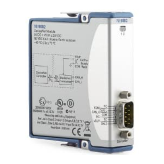
- Page 1 OPERATING INSTRUCTIONS NI 9882 1-Port DeviceNet Module...
-
Page 2: Safety Guidelines
Refer to the documentation for each component in your system to determine the safety ratings and specifications for the entire system. Safety Guidelines Operate the NI 9882 only as described in these operating instructions. This icon denotes that the component may be Hot Surface hot. - Page 3 Safety Guidelines for Hazardous Locations The NI 9882 is suitable for use in Class I, Division 2, Groups A, B, C, D, T4 hazardous locations; Class I, Zone 2, AEx nA II T4 and Ex nA II T4 hazardous locations; and nonhazardous locations only.
-
Page 4: Wiring The Ni 9882
Wiring the NI 9882 The NI 9882 has one 9-pin male D-Sub connector that provides connections to a CAN bus. The NI 9882 has pins for CAN_H and CAN_L, to which you connect the CAN bus signals. Connect these signals using twisted-pair cable. - Page 5 Caution marked LPS with the NI 9882. The NI 9882 requires an external power supply in the range of +9 to +30 V to operate. Supply power to the NI 9882 V pin. Power on V is required for DeviceNET Note operation.
- Page 6 Table 1. Pin Assignments for the NI 9882 Connector Signal No Connection (NC) CAN_L SHLD CAN_H NI 9882 Operating Instructions ni.com...
- Page 7 Figure 1 shows a simplified diagram of a CAN bus with multiple CAN nodes and proper termination resistor (R ) locations. © National Instruments Corp. NI 9882 Operating Instructions...
- Page 8 Bus Cable Length CAN_H CAN_H Node Node CAN_L CAN_L Stub Length Node Node Figure 1. CAN Bus Topology and Termination Resistor Locations NI 9882 Operating Instructions ni.com...
-
Page 9: Cabling Requirements For The Ni 9882
Connecting a CAN Bus to the NI 9882 You can connect the NI 9882 port to any location on a CAN bus. Figure 2 shows one example of connecting the NI 9882 directly to one CAN node. (SHLD) (SHLD) CAN_H... -
Page 10: Cable Specifications
CAN cable and therefore comply with the values in Table 3. The onboard, software-selectable termination has a nominal value of 120 . If you are not using the onboard termination, use the values listed in Table 3. NI 9882 Operating Instructions ni.com... -
Page 11: Cable Lengths
0.3 m for a bit rate of 1 Mb/s. The ISO 11898 specification says that significantly longer cable lengths may be allowed at lower bit rates, but you should analyze each node for signal integrity problems. © National Instruments Corp. NI 9882 Operating Instructions... -
Page 12: Ni 9882 Hardware Overview
You can connect higher numbers of nodes if the nodes’ electrical characteristics do not degrade signal quality below ISO 11898 signal level specifications. The NI 9882 electrical characteristics allow at least 110 CAN ports on a network. NI 9882 Hardware Overview The NI 9882 has one full-featured DeviceNet port that is isolated from the other modules in the system. -
Page 13: Sleep Mode (Compactrio Only)
DeviceNet CAN_L Transceiver Controller Figure 3. NI 9882 Hardware Overview Sleep Mode (CompactRIO Only) You can enable sleep mode for the CompactRIO system in software. In sleep mode, the system consumes less power and may dissipate less heat. When a system is in sleep mode, you cannot communicate with the modules. -
Page 14: Specifications
Supply voltage range (V CAN ........... +9 to +30 VDC MTBF ..........Contact NI for Bellcore MTBF or MIL-HDBK-217F specifications. Power Requirements Power consumption from chassis Active mode ....... 1 W max Sleep mode ......... 2.55 mW max NI 9882 Operating Instructions ni.com... -
Page 15: Physical Characteristics
This category is for measurements of voltages from specially protected secondary The maximum voltage that can be applied or output between any port or V terminal and a COM terminal without creating a safety hazard. © National Instruments Corp. NI 9882 Operating Instructions... - Page 16 Measurement Category I Safety Standards This product meets the requirements of the following standards of safety for electrical equipment for measurement, control, and laboratory use: • IEC 61010-1, EN 61010-1 • UL 61010-1, CSA 61010-1 NI 9882 Operating Instructions ni.com...
- Page 17 Refer to the installation instructions for the chassis you are using for more information about meeting these specifications. Operating temperature ...... – 40 to 70 °C Storage temperature ......– 40 to 85 °C Ingress protection......IP 40 © National Instruments Corp. NI 9882 Operating Instructions...
-
Page 18: Shock And Vibration
Operating shock (IEC 60068-2-27)......30 g, 11 ms half sine, 50 g, 3 ms half sine, 18 shocks at 6 orientations Operating vibration, sinusoidal (IEC 60068-2-6) ....5 g, 10 to 500 Hz NI 9882 Operating Instructions ni.com... -
Page 19: Electromagnetic Compatibility
ICES-001: Class A emissions For the standards applied to assess the EMC of this Note product, refer to the Online Product Certification section. For EMC compliance, operate this product Note according to the documentation. © National Instruments Corp. NI 9882 Operating Instructions... -
Page 20: Online Product Certification
Certification column. Environmental Management NI is committed to designing and manufacturing products in an environmentally responsible manner. NI recognizes that eliminating certain hazardous substances from our products is beneficial to the environment and to NI customers. NI 9882 Operating Instructions ni.com... - Page 21 At the end of the product life cycle, all EU Customers products must be sent to a WEEE recycling center. For more information about WEEE recycling centers, National Instruments WEEE initiatives, and compliance with WEEE Directive 2002/96/EC on Waste and Electronic Equipment, visit ni.com/...
-
Page 22: Where To Go For Support
Where to Go for Support The National Instruments Web site is your complete resource for technical support. At you have access to ni.com/support everything from troubleshooting and application development self-help resources to email and phone assistance from NI Application Engineers. - Page 23 South Africa 27 0 11 805 8197, Spain 34 91 640 0085, Sweden 46 (0) 8 587 895 00, Switzerland 41 56 2005151, Taiwan 886 02 2377 2222, Thailand 662 278 6777, Turkey 90 212 279 3031, United Kingdom 44 (0) 1635 523545 © National Instruments Corp. NI 9882 Operating Instructions...
- Page 24 LabVIEW, National Instruments, NI, ni.com, the National Instruments corporate logo, and the Eagle logo are trademarks of National Instruments Corporation. Refer to the Trademark Information at ni.com/trademarks for other National Instruments trademarks. Other product and company names mentioned herein are trademarks or trade names of their respective companies.
Need help?
Do you have a question about the NI 9882 and is the answer not in the manual?
Questions and answers