
Related Manuals for Garnet SPILLSTOP ULTRA 815-UHP


Summary of Contents for Garnet SPILLSTOP ULTRA 815-UHP
- Page 1 PILL L TRA Alarm Controller with Hose Protection Overfill Prevention System MODEL 815-UHP PTO VERSION MANUAL Printed in Canada www.garnetinstruments.com...
-
Page 2: Table Of Contents
GARNET PILL L TRA Hose Protection Overfill Prevention System MODEL 815-UHP PTO VERSION MANUAL Table of Contents CHAPTER 1 - OVERVIEW .....................3 CHAPTER 2 - FEATURES AND OPERATION ............4 CHAPTER 3 - INSTALLATION GUIDE ...............8 CHAPTER 4 - WIRING DIAGRAMS ................. 11 CHAPTER 5 - TROUBLESHOOTING GUIDE ............ -
Page 3: Chapter 1 - Overview
System. The 815UHP represents the state of the art in spill control for crude oil and chemical hauling. The S ™ is designed PILLSTOP to work in conjunction with a Garnet Model 810PS2 S ™ or a Model 808P2 S ™ system to assist ERIES... -
Page 4: Chapter 2 - Features And Operation
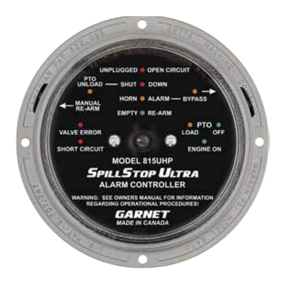
CHAPTER 2 - FEATURES AND OPERATION he following diagram shows the basic components and connections of the 815UHP for a tractor trailer application. A body truck application would be similar except that the 7 pin plug & socket would not be required since the tank is never disconnected from the truck. - Page 5 The operation of the SPILLSTOP UHP system during loading with a PTO driven pump is as follows: When the tank is empty and the PTO is disengaged, the green EMPTY/RE-ARM indicator is on, the green PTO OFF indicator is on, the green ENGINE ON indicator is on, the horn is off, and the engine is allowed to run.
- Page 6 prevents sloshing or other disturbances from sounding the horn or killing the engine during driving. The horn alarm bypass is cleared whenever the system is powered up, regardless of the fluid level. This means that if the system is powered off prior to unloading and the fluid level is above the horn alarm point, then the horn will sound and the engine will not be allowed to run on power up and PTO engagement.
- Page 7 The horn configuration wire on the controller allows different horn operation options. If the wire is connected to ground or left open, then the horn will always sound in response to a horn alarm condition regardless of whether the PTO is engaged or disengaged. Conversely, if the wire is connected to +12V, then the horn will only sound when the PTO is engaged in either the loading or unloading position.
-
Page 8: Chapter 3 - Installation Guide
Complete the wiring in accordance with the applicable wiring diagram supplied by Garnet. 7. Program the alarm points in the gauge. Program alarm #1 as SHUT DOWN at the point beyond which loading is not permitted. - Page 9 empty point right at the bottom, since any buildup of debris on the anchor will prevent the system from clearing the bypasses. See the 808P2 or 810PS2 manual for programming details. Example: The tank is 58 inches high, with a bottom reading of 4.6 inches.
- Page 10 Complete the wiring in accordance with the applicable wiring diagram supplied by Garnet. 6. Program the alarm points in the gauge. Program alarm #1 as SHUT DOWN at the point beyond which loading is not permitted.
-
Page 11: Chapter 4 - Wiring Diagrams
USE ONLY SWITCHES AVAILABLE (SWITCH CLOSED UNLOADING. NORMALLY CLOSED WHEN PRESSURE TRAILER MOUNTED TRAILER WHEN PTO ENGAGED) FROM GARNET TECHNOLOGIES. IS LOW. (SWITCH OPENS WHEN THERE IS A FAULT) PRESSURE SWITCH ACTIVATED BY GROUND NON APPROVED SWITCHES MAY HOSE PRESSURE ON DISCHARGE OF EITHER OF THESE HOSE PROTECTION SWITCHES CAN BE FAIL PREMATURELY. - Page 12 Wiring Guide - Main Connector Red: +12V power Black: Ground Orange: Horn alarm output Green: Shutdown alarm output Yellow: signal from the 808P2/810PS2 gauge PILL Purple: (connected) Horn Bypass switch White: (connected) Manual Re-arm switch Wiring Guide - Sensor Connector White/Orange: Hose protection switch White/Blue:...
-
Page 13: Chapter 5 - Troubleshooting Guide
CHAPTER 5 - TROUBLESHOOTING GUIDE If problems are encountered, check the following: 1. Is the controller getting at least 8 volts? 2. Are all the wires properly connected, with no short circuits? 3. Are the 808P2 or 810PS2 S L gauges working properly? 4. -
Page 14: Chapter 6 - Service And Warranty Information
Alberta, T8A 4G7. Returned warranted items will be repaired or replaced at the discretion of Garnet Instruments. Any Garnet items under the Garnet Warranty Policy that are deemed irreparable by Garnet Instruments will be replaced at no charge or a credit will be issued for that item subject to the customer’s request. -
Page 15: Mail In Warranty
MAIL IN WARRANTY... - Page 16 Printed in Canada CANADA Garnet Instruments Ltd. P: 780-467-1010 Garnet US Inc. P: 817-578-8601 286 Kaska Road F: 780-467-1567 5360 Old Granbury Road F: 817-573-0005 www.garnetinstruments.com Sherwood Park, AB T8A 4G7 TF: 1-800-617-7384 Granbury, TX 76049 TF: 1-877-668-7813...
Need help?
Do you have a question about the SPILLSTOP ULTRA 815-UHP and is the answer not in the manual?
Questions and answers