
Related Manuals for Garnet SPILLSTOP ULTRA 815-U


Summary of Contents for Garnet SPILLSTOP ULTRA 815-U
- Page 1 PILL L TRA Overfill Prevention System MODEL 815-U MANUAL Printed in Canada www.garnetinstruments.com 815U Manual Page 1...
-
Page 2: Table Of Contents
GARNET PILL L TRA Overfill Prevention System MODEL 815-U MANUAL Table of Contents CHAPTER 1 - OVERVIEW ..............3 CHAPTER 2 - FEATURES AND OPERATION ......... 4 CHAPTER 3 - INSTALLATION GUIDE ........... 7 CHAPTER 4 - WIRING DIAGRAMS ............11 CHAPTER 5 - TROUBLESHOOTING GUIDE ......... -
Page 3: Chapter 1 - Overview
CHAPTER 1 - OVERVIEW ongratulations on purchasing the Garnet Instruments Model 815 S ™ overfill prevention system. PILL LTRA represents the state of the art in spill control for crude PILL oil and chemical hauling. The S ™ is designed to work in... -
Page 4: Chapter 2 - Features And Operation
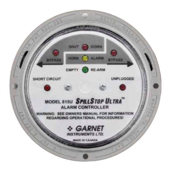
CHAPTER 2 - FEATURES AND OPERATION he following sketch shows the basic components and connections of the S for a tractor trailer application. PILL A body truck application would be similar except that the 7 pin plug & socket would not be required since the tank is never disconnected from the truck. - Page 5 WARNING: The S is intended as an emergency PILL LTRA backup system only, and is not intended as a substitute for operator diligence during the loading process. The operation of the S Ultra during the loading operation PILL is as follows: When the tank is empty, the green EMPTY/RE- ARM indicator is on, the horn is off, and the engine or pump is allowed to run.
- Page 6 controller cannot be corrupted by poor connections or moisture in the wiring; if the signal is too badly degraded it defaults directly to an open or short circuit condition. A failure of the S L or L Special gauge causes the controller to default to the horn alarm and shut down condition.
-
Page 7: Chapter 3 - Installation Guide
CHAPTER 3 - INSTALLATION GUIDE efer to the appropriate wiring diagram during installation of the S system. The wiring diagrams are in chapter 4. PILL Follow these instructions for a tractor trailer installation: 1. Pick a spot for the S Ultra controller to be mounted. - Page 8 auxiliary ESD relay (supplied). Connect one of the auxiliary ESD relay coil terminals (#86) to the 12 volt source and the other coil terminal (#85) to the green wire in the controller. It is a good idea to mount the auxiliary ESD relay close to the existing shutoff wiring to minimize any extra wire length in the truck shutoff circuit.
- Page 9 Follow these instructions for a body truck installation: 1. Pick a spot for the S Ultra controller to be mounted. PILL It can be inside or outside of the cab. Do not mount the controller where it can be kicked and it should be easy to see and out of direct road spray.
- Page 10 8. Connect the 815U controller’s orange wire to the truck’s electrical horn switch (or button). Make sure that grounding this connection will cause the horn to sound. This connection is normally to the horn relay coil, not to the horn itself. 9.
-
Page 11: Chapter 4 - Wiring Diagrams
CHAPTER 4 - WIRING DIAGRAMS SINGLE COMPARTMENT WIRING DIAGRAM WITH PTO PRESSURE SWITCH APPLICATION PTO PRESSURE SWITCH (CLOSED WHEN PTO ENGAGED) SeeLeveL INDICATOR Special LIGHT GAUGE BLACK GREEN COIL NOTE: Relay contacts 30 and 87A are the SENSE normally closed (NC) contacts. #87A RELAY Relay contacts 30 and 87 are the... -
Page 12: Chapter 5 - Troubleshooting Guide
CHAPTER 5 - TROUBLESHOOTING GUIDE F problems are encountered, check the following: 1. Is the controller getting at least 8 volts? 2. Are all the wires properly connected, with no short circuits? 3. Are the 808P2 or 810PS2 S L gauges working properly? 4. -
Page 13: Chapter 6 - Service And Warranty Information
Garnet or an Authorized Dealer. The warranty period will start from the date of purchase or installation as indicated on the warranty card. Under these warranties, Garnet shall be responsible only for actual loss or damage suffered and then only to the extent of Garnet’s invoiced price of the product. -
Page 15: Mail In Warranty
MAIL IN WARRANTY... - Page 18 Printed in Canada CANADA Garnet Instruments Ltd. Garnet Technologies Inc. P: 780-467-1010 P: 817-578-8601 286 Kaska Road 201 M&M Ranch Road F: 780-467-1567 F: 817-573-0005 www.garnetinstruments.com Sherwood Park, AB T8A 4G7 Granbury, TX 76049 TF: 1-800-617-7384 TF: 1-877-668-7813...
Need help?
Do you have a question about the SPILLSTOP ULTRA 815-U and is the answer not in the manual?
Questions and answers