Table of Contents
Advertisement
Available languages
Available languages
Quick Links
Advertisement
Chapters
Table of Contents

Subscribe to Our Youtube Channel
Related Manuals for HAMPTON BAY Asbury Plus


Summary of Contents for HAMPTON BAY Asbury Plus
-
Page 2: Table Of Contents
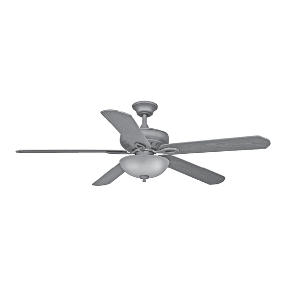
60” Asbury Plus Thank you for purchasing this Hampton Bay ceiling fan. This product has been manufactured with the highest standards of safety and quality. The finish Ceiling Fan by Hampton Bay of this fan is weather resistant, but over time will naturally weather and fade. -
Page 3: Safety Rules 1
READ AND SAVE THESE INSTRUCTIONS To avoid personal injury or damage to the fan and other items, To reduce the risk of electric shock, insure electricity be cautious when working around or cleaning the fan. has been turned off at the circuit breaker or fuse box before beginning. -
Page 4: Unpacking Your Fan
Unpack your fan and check the contents. You should have the following items: Blade attachment hardware 1. Slide-On Mounting Plate (inside canopy) 7. Glass Bowl (15 screws) 2. Canopy with Canopy Ring attached 8. Bulbs (3) Electrical & Mounting Hardware 3. -
Page 5: Installing Your Fan 3
Figure 4 LIGHTING FIXTURES MAY NOT BE ACCEPT- ABLE FOR FAN SUPPORT AND MAY NEED TO (available at your Hampton Bay retailer). BE REPLACED. CONSULT A QUALIFIED ELEC- TRICIAN IF IN DOUBT. Installing Your Fan 3. - Page 6 Hanging the Fan different procedures to follow for the two 3. Route the wires exiting the top of the fan motor through the decorative motor types of installation. REMEMBER collar cover then the canopy ring. Make sure turn pow- Standard Ceiling Mounting the slot openings are on top.
- Page 7 “Close-to-Ceiling” Mounting 4. Loosen, but do not remove, the set 6. Align the mounting holes with the holes screw on the collar on the top of the in the motor and fasten, using the three 1. Remove the canopy ring from the canopy motor housing.
- Page 8 Making the Electrical ing mounting plate. If using Close-to- Ceiling mounting, hang the fan on the Connections WHEN USING THE STANDARD BALL/DOWNROD hook provided by utilizing one of the MOUNTING, THE TAB IN THE RING AT THE BOT- holes at the outer rim of the ceiling canopy TOM OF THE MOUNTING PLATE MUST REST IN REMEMBER to disconnect the power.
- Page 9 Finishing the Fan 6. Connect the receiver white wire to the sup- SUPPLY CIRCUIT ply white wire (neutral) wire using a wire Installation nut (Figure 13). 7. After connecting the wires, spread them STANDARD CEILING MOUNTING apart so that the green and white wires are Switch one side of the outlet box and the black wire is on the other side.
- Page 10 Attaching the CLOSE-TO-CEILING MOUNTING 1. Carefully unhook the fan from the mount- Fan Blades ing plate and align the locking slots of the ceiling canopy with the two screws in the NOTE: Your fan blade are reversible. Select mounting plate. Push up to engage the slots the blade side finish which best accentuates and turn clockwise to lock in place.
- Page 11 Light Kit Option 4. Align the three screw holes in the switch cup cover with the screw holes in the switch CAUTION - To reduce the risk of electrical cup. Position the switch cup cover onto the shock, disconnect the electrical supply circuit switch cup and install the three screws that to the fan before installing light kit.
- Page 12 Fan Without Light Kit Blade Balancing All blades are grouped by weight. Because nat- 1. In order to use the fan without the light kit, ural woods vary in density, the fan may wobble remove the switch cup cover from the top even though the blades are weight matched.
-
Page 13: Operating Your Remote Control 11
Operating the Fan: Remote Control Setting the Code Your fan is equipped with a remote control This unit has 16 different code combinations. Hi Key - High Speed To set the code, perform the following steps: to operate the speed and lights of your new Med Key - Medium Speed A. -
Page 14: Operating Your Fan
Turn on the power and check the operation of the fan. Speed settings for warm or cool weather depend on factors such as room size, ceiling height, number of fans, and so on. The slide switch controls the direction: forward (switch down) or reverse (switch up). -
Page 15: Care Of Your Fan
Troubleshooting Care of Your Fan Here are some suggestions to help you Problem Solution maintain your fan. Fan will not start Check main and branch circuit fuses or breakers 1. Because of the fan’s natural movement, Check line wire connections to the fan and switch wire connections in some connections may become loose. -
Page 16: Specifications
GROSS FAN SIZE SPEED VOLTS AMPS WATTS CUBE FEET WEIGHT WEIGHT 0.34 2499 26.0 29.3 60” 0.45 3725 2.4’ High 0.54 5699 These are approximate measures. They do not include Amps and Wattage used by the light kit. Distributed by Your Other Warehouse LLC 12100 Little Cayman Dr. -
Page 17: Warranty Information 15
You must present a copy of the original Hampton Bay also warrants that all other fan parts, excluding any glass or acrylic blades, to be free purchase receipt to obtain warranty service. - Page 18 Asbury Plus de 60” Gracias por comprar este ventilador de techo de Hampton Bay. Este producto se ha fabricado con las normas de seguridad y calidad más altas. El acabado Ventilador de techo de Hampton Bay de este ventilador es resistente a la intemperie, pero con el tiempo, exhibirá...
-
Page 19: Normas De Seguridad
LEE LAS INSTRUCCIONES Y GUÁRDALAS Para disminuir el riesgo de descarga eléctrica, asegúrate de Evita colocar objetos en la trayectoria de las aspas. que la electricidad ha sido apagada en el cortacircuitos o Para evitar lesiones, o daños al ventilador y otros objetos; ten la caja de fusibles antes de comenzar la instalación. -
Page 20: Cómo Desempacar El Ventilador 2
Desempaca tu ventilador y revisa el contenido. Deberá tener las siguientes piezas: Herrajes de montaje de aspas (15 tornillos) 1. Placa de montaje deslizante (dentro de la 5. Ensamblado del motor del ventilador Herrajes de montaje y electricidad cubierta) 6. Aspas (5) 2. -
Page 21: Cómo Instalar El Ventilador
ARTÍCULOS DE ILUMINACIÓN PUEDEN NO SERVIR como se muestra en la Figura 4 (disponible en COMO SOPORTE DE VENTILADOR, Y TAL VEZ DEBAN REEMPLAZARSE. EN CASO DE DUDA, CONSULTA A la tienda minorista local de Hampton Bay). UN ELECTRICISTA CALIFICADO. 3. Cómo instalar el ventilador... - Page 22 Cómo colgar el necesario, cada sección de las instrucciones luego, por el aro de la cubierta. Asegúrate de indicará los diferentes procedimientos a seguir que las aberturas en forma de ranura estén en ventilador para los dos tipos de instalación. la parte superior.
- Page 23 Montaje “Cerca del Techo” 4. Afloja, sin quitarlo, el tornillo en el collarín orificios del motor y asegura con los tres ubicado en la parte superior de la carcasa del tornillos y arandelas de seguridad retiradas 1. Retira el aro en la cubierta, girando a la motor.
- Page 24 Cómo hacer las 3. Ajusta firmemente los dos tornillos de montaje. conexiones eléctricas CUANDO USES EL MONTAJE DE TUBO BAJANTE Y 4. Con cuidado alza el ensamblado hasta BOLA ESTÁNDAR, LA PESTAÑA EN EL ARO EN LA la placa de montaje. Si usas el montaje PARTE INFERIOR DE LA PLACA DE MONTAJE DEBE RECUERDA desconectar la electricidad.
- Page 25 Finalizar la instalación usando una tuerca de cable (Figura 13). CIRCUITO DE SUMINISTRO 6. Conecta el cable blanco del receptor al del ventilador cable blanco de energía (neutro) usando una MONTAJE DE TECHO tuerca de cable (Figura 13). Interruptor 7. Después de conectar los cables, sepáralos ESTÁNDAR de manera que los cables verde y blanco Caja eléctrica...
- Page 26 Cómo montar el soporte del aspa. Inserta el tornillo en el MONTAJE CERCA DEL TECHO soporte. Repite para los otros dos tornillos. 1. Con cuidado desengancha el ventilador de las aspas del 6. Aprieta todos los tornillos de manera firme. la placa de montaje y alinea las ranuras de cierre de la cubierta del techo con los dos ventilador...
- Page 27 Opción del kit de luces 3. Conecta los cables del soporte del kit de luces a los cables de la caja del interruptor PRECAUCIÓN – Para disminuir el riesgo de del ensamblado del motor, al conectar los descarga eléctrica, desconecta el circuito de enchufes con adaptadores moldeados (azul energía del ventilador antes de instalar el kit de con negro, blanco con blanco).
- Page 28 Ventilador muestra en la Figura 19. Rota el ventilador hasta que se posicione la siguiente aspa para sin kit de luces su medición. Repite para cada aspa. Las desviaciones de la medición deben estar 1. Con el fin de utilizar el ventilador sin el dentro de 1/8”.
-
Page 29: Cómo Usar El Control Remoto
Control remoto Cómo configurar Cómo poner en funcionamiento el código Tu ventilador está equipado con un control el ventilador: remoto que controla la velocidad y las Esta unidad tiene 16 combinaciones de códigos luces de tu ventilador de techo. Para más diferentes. -
Page 30: Cómo Operar El Ventilador 12
Enciende electricidad verifica funcionamiento del ventilador. Las configuraciones de velocidad para clima cálido o frío dependen de factores como tamaño de la habitación, altura del techo, cantidad de ventiladores y demás. El interruptor deslizable controla la dirección: hacia adelante (interruptor hacia abajo) o reversa (interruptor hacia arriba). -
Page 31: Cuidado Del Ventilador
Solución de problemas Cuidado del ventilador Aquí tienes algunas sugerencias para el Problema Solución mantenimiento de tu ventilador. El ventilador no 1. Debido al movimiento natural del ventilador, Verifica fusibles o disyuntores principales y secundarios. algunas conexiones pueden aflojarse. enciende Verifica conexiones de cables en línea al ventilador y conexiones de Revisa las conexiones de soporte, soportes cables del interruptor en la caja de interruptores. -
Page 32: Especificaciones 14
PIES PESO PESO TAMAÑO VELOCIDAD VOLTIOS AMPERIOS VATIOS CÚB. X PIES CÚB. NETO BRUTO MIN. Baja 0.34 2499 26.0 29.3 60” Media 0.45 3725 2.4’ Alta 0.54 5699 Estas medidas son aproximadas. No incluyen ni el amperaje ni el vataje consumido por el kit de luces. Distribuido por Your Other Warehouse LLC 12100 Little Cayman Dr. -
Page 33: Información De La Garantía
Hampton Bay garantiza de por vida, a partir de la fecha de compra por el comprador original, que el motor del ventilador no presenta defectos de fabricación ni de material desde la fecha de salida de Usted debe presentar una copia del la fábrica.
Need help?
Do you have a question about the Asbury Plus and is the answer not in the manual?
Questions and answers