Advertisement
Advertisement
Table of Contents

Related Manuals for HAMPTON BAY Ansley


Summary of Contents for HAMPTON BAY Ansley
-
Page 1: Ceiling Fan
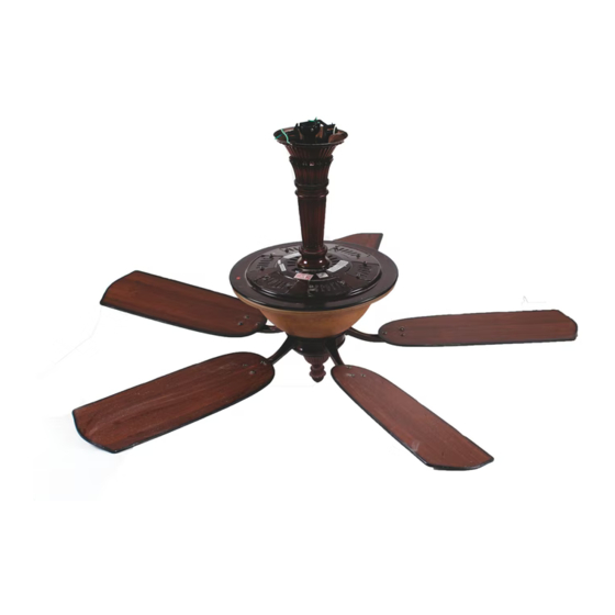
761 512 Ansley Ceiling Fan Owner’s Manual Ansley Ventilador de Techo de 1,32 Manual del Propietario... -
Page 2: Table Of Contents
52” Ansley Thank you for purchasing our ceiling fan. This product has been manufactured with the highest standards of safety and quality. Ceiling Fan by Hampton Bay Date Purchased Store Purchased Table of Contents 761-512 Safety Rules ....1 UL Model No. -
Page 3: Safety Rules
Safety Rules - Read and Save These Instructions To reduce the risk of electric shock, insure electricity has been turned off After making electrical connections, spliced conductors should be turned at the circuit breaker or fuse box before beginning. upward and pushed carefully up into outlet box. The wires should be spread apart with the grounded conductor and the equipment-grounding All wiring must be in accordance with the National Electrical Code conductor on one side of the outlet box and ungrounded conductor on the... -
Page 4: Unpacking Your Fan
Unpacking Your Fan Unpack your fan and check the contents. You should have the following items: Set of blades (5) Coupling cover (for close to ceiling Blade Attachment Hardware (16 Screws with Fiber Washers) Canopy assembly mounting) Standard downrod assembly Fan motor assembly Electrical Hardware Minimum-length downrod (for close to... -
Page 5: Installing Your Fan
Installing Your Fan Provide Strong Support Tools Required Figures 1~3 are examples of different ways to mount the outlet box. Phillips screwdriver, straight slot screwdriver, step ladder and wire cutters. Recessed Ceiling Outlet Box Mounting Plate Mounting Options Figure 3 Outlet Box Note: You may need a longer downrod to If there isn't an existing UL listed mounting box,... -
Page 6: Hanging The Fan
Hanging the Fan Tighten two set screws at top of the fan motor Follow the Figure 6 and continue on section titled collar firmly and evenly. (Fig. 6) "Hanging the Fan" for installation. REMEMBER to turn off the power. Follow the WARNING steps below to hang your fan properly. -
Page 7: Installing Fan To The Electrical Box
Installing the fan without arrow style Pass the 120-volt supply wires through the Motor Wires decorative downrod (with 4-1/2" center hole in the ceiling mounting bracket as downrod) (Recommend min. 8.25 ft ceiling shown in Figure 7. Pin in Locked Ceiling Canopy height). - Page 8 Follow the steps below to connect the fan to your SUPPLY CIRCUIT household wiring. Use the wire nuts supplied with your fan. Secure the wire nuts with electrical tape. Make sure there are no loose strands or connections. Ground Conductor Connect the fan supply (black) wire to the black household supply wire as shown in Figure 9.
-
Page 9: Glass Shade
Finishing the Fan holes. Secure the glass housing assembly by Outlet box tightening the 2 screws loosened and the one Installation removed previously. (Fig. 11) Ceiling Mounting Tuck connections neatly into ceiling outlet Bracket box. Screws Slide the canopy up to ceiling and over the 2 Canopy screws on the mounting bracket. - Page 10 Attaching the Fan Blades WARNING TO REDUCE THE RISK OF PERSONAL INJURY, DO NOT BEND THE BLADE ARMS WHILE Attach blades to blade arms using three screws Motor INSTALLING, BALANCING THE BLADES, OR with fiber washers (Fig. 12). Start a screw into CLEANING THE FAN.
-
Page 11: Blade Balancing
Blade Balancing The following procedure should correct most fan wobble. Check after each step. Touching Ceiling Check that all blade and blade bracket screws are secure. Most fan wobble problems are caused when blade levels are unequal. Check this level by selecting a point on the ceiling above the tip of one of the blades. - Page 12 Installing the Decorative Interior Bulb Replacement Cover REMEMBER to turn off the power. Remove the 2 screws from the bulb access REMEMBER: In order to install the decorative cover and take the bulb access cover off from cover, the fan blades must already be attached to the top decorative housing as shown in Figure the fan.
-
Page 13: Operating Your Transmitter
Operating Your Transmitter Restore power to the ceiling fan and test for proper operation. "HI, MED, LOW" buttons: Installing the Battery The receiver frequency selectoris located on These three buttons are used to set the fan the top of the motor assembly plate as show in speed as follows: Fig. - Page 14 The " ": button is used to set the fan forward or reverse, press the button forward (for warm weather) or reverse (for cool weather) Speed settings for warm or cool weather depend on factors such as the room size, ceiling height, number of fans, etc.
-
Page 15: Care Of Your Fan
Care of Your Fan Troubleshooting PROBLEM SOLUTION Here are some suggestions to help you maintain your fan. Fan will not start Check main and branch circuit fuses or breakers. Because of the fan's natural movement, some Check line wire connections to the fan and switch wire connections in connections may become loose. -
Page 16: Specifications
Specifications FAN SIZE SPEED VOLTS AMPS WATTS N.W. G.W. C.F. 0.27 2005 13.5 kgs 15.7 kgs 52” MED. 0.42 3946 2.94’ (29.6 Ibs) (34.5 Ibs) HIGH 0.58 6125 These are approximate measures. They do not include Amps and Wattage used by the light kit . -
Page 17: Warranty Information
Lifetime Limited Warranty (lifetime warranty on motor) The Hampton Bay warrants the fan motor to be free from defects in workmanship and material present at time You must present a copy of the original purchase receipt to obtain warranty of shipment from the factory for a period of lifetime after the date of purchase by the original purchaser.
Need help?
Do you have a question about the Ansley and is the answer not in the manual?
Questions and answers
what are the specs. for my hampton bay ansley fan capacitor, number of wires, uf and voltage,etc.
Where is the capacitor located