Advertisement
Quick Links
USE AND CARE GUIDE
Questions, problems, missing parts? Before returning to the store,
8 a.m. - 7 p.m., EST, Monday-Friday, 9 a.m. - 6 p.m., EST Saturday
We appreciate the trust and confidence you have placed in Hampton Bay through the purchase of this ceiling fan. We strive to
continually create quality products designed to enhance your home. Visit us online to see our full line of products available for
your home improvement needs. Thank you for choosing Hampton Bay!
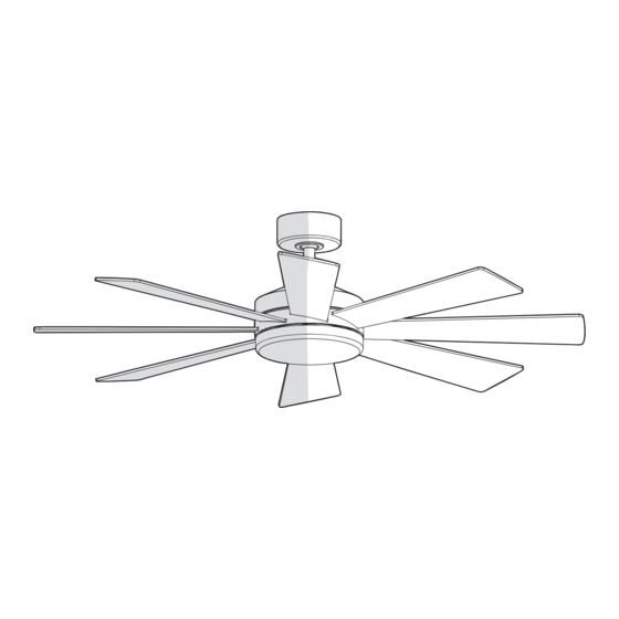
52 IN. BAYLA
INDOOR CEILING FAN
call Hampton Bay Customer Service
1-855-HD-HAMPTON
HAMPTONBAY.COM
Visual instruction of how to install this fan:
Visit www.homedepot.com and enter either the Item or Model number to find
this fan and click the link of visual instruction in the product overview section.
THANK YOU
Item #1008 656 772
1008 656 503
Model #AK401A-BN
AK401A-MBK
Advertisement

Related Manuals for HAMPTON BAY AK401A-BN


Summary of Contents for HAMPTON BAY AK401A-BN
- Page 1 THANK YOU We appreciate the trust and confidence you have placed in Hampton Bay through the purchase of this ceiling fan. We strive to continually create quality products designed to enhance your home. Visit us online to see our full line of products available for...
-
Page 2: Table Of Contents
Model Number: AK401A-BN, AK401A-MBK All wiring must be in accordance with the National Electrical Company Name: TAL INTERNATIONAL CORPORATION Code “ANSI/NFPA 70” and local electrical codes. Electrical Company Address: 2919 E. -
Page 3: Warranty
Warranty The manufacturer warrants the fan motor to be free from defects in workmanship and material present at time of shipment from the factory for a period of lifetime after the date of purchase by the original purchaser. The manufacturer warrants the light kit (excluding any glass), to be free from defects in workmanship and material at the time of shipment from the factory for a period of three years after the date of purchase by the original purchaser. - Page 4 Pre-Installation (continued) HARDWARE INCLUDED NOTE: Hardware not shown to actual size. Part Description Quantity Plastic wire nut Blade attachment screw and lock washer (additional) 1.5V AAA battery 3-pin extension cord...
- Page 5 Pre-Installation (continued) PACKAGE CONTENTS ON / OFF ON / OFF 3 SPEED BRIGHTNESS COLOR TEMP. Part Description Quantity Part Description Quantity Mounting bracket (preassembled) Blade Canopy Blade support plate with screw and lock washer Canopy bottom cover (preassembled) Hanger ball/downrod assembly 20 watt LED light kit Coupling cover Receiver...
-
Page 6: Installation
Installation MOUNTING OPTIONS NOTE: You may need a longer downrod to maintain proper WARNING: To reduce the risk of fire, electric shock, or blade clearance when installing on a steep, sloped ceiling. personal injury, mount the fan to an outlet box marked The maximum angle allowable is 18°... -
Page 7: Assembly
Assembly Preparing the canopy Preparing the motor Remove the cotter pin (FF) and clevis pin (GG), and loosen Remove the canopy bottom cover (C) from the canopy (B) by the two collar setscrews (HH) from the fan motor assembly turning the canopy bottom cover (C) counterclockwise. (F) collar. - Page 8 Assembly — Hanging the Fan Attaching the mounting bracket to the Hanging the fan on the mounting electrical box bracket WARNING: To reduce the risk of fire, electric shock or other WARNING: The tab in the ring must rest in the groove of personal injury, mount the fan only to an outlet box or supporting the hanger ball/downrod assembly (D).
- Page 9 Assembly — Hanging the Fan (continued) Making the electrical connections Ground conductor White Black WARNING: Check to see that all connections are tight, including ground, and that no bare wire is visible at the wire nuts, except for the ground wire. Outlet Box CAUTION: Do not use with a wall light dimmer switch.
- Page 10 Assembly — Hanging the Fan (continued) Installing the canopy Attaching the canopy bottom cover NOTE: Adjust the canopy mounting screws (EE) as necessary WARNING: Make sure the tab on the mounting bracket (A) until the canopy (B) and canopy bottom cover (C) are snug. properly sits in the groove in the hanger ball (D) before attaching the canopy (B) to the mounting bracket (A) by turning the canopy housing until it drops into place.
- Page 11 Assembly — Attaching the Fan Blades Attaching the fan blades WARNING: To reduce the risk of personal injury, do not bend the blades (G) while installing, balancing the blades (G) or cleaning the fan. or cleaning the fan. WARNING: Do not insert foreign objects between rotating fan blades (G).
-
Page 12: Operation
Operation SETTING THE TRANSMITTER NOTE: The remote has been pre-paired in the factory for your convenience. NOTE: Batteries will weaken with age and should be replaced before leaking takes place as this will damage the remote control. Dispose of used batteries properly and keep them out of the reach of children. - Page 13 Operation (continued) OPERATING YOUR FAN AND REMOTE CONTROL NOTE: The fan will store the last used speed setting for the next time it is turned on. Signal light Power on/off Power ALL button: Press and release the power button to turn Fan on/off the fan and light on or off.
- Page 14 Operation (continued) INSTALLING THE REMOTE CONTROL HOLDER To install the remote control bracket (PP), remove the two screws holding the switch cover plate (QQ). Do not remove the cover plate (QQ). Orient the bracket (PP) by lining up the two mounting holes with those on the cover plate (QQ).
- Page 15 Operation (continued) REVERSE SWITCH OPERATING INSTRUCTIONS The reverse switch is located on the surface of the motor housing. Reverse switch Slide the switch to the left for warm weather operation. Slide the switch to the right for cool weather operation. NOTE: Wait for the fan to stop before reversing the direction of the blade rotation.
-
Page 16: Care And Cleaning
Care and Cleaning Check the support connections, brackets, and blade attachments twice a year. Make sure they are secure. Because of the fan’s natural movement, some connections may become loose over time. It is not necessary to remove the fan from the ceiling. Clean your fan periodically. - Page 17 - Consult the dealer or an experienced radio/TV technician for help. Questions, problems, missing parts? Before returning to the store, call Hampton Bay Customer Service 8 a.m. – 7 p.m., EST, Monday – Friday, 9 a.m. – 6 p.m., EST, Saturday 1-855-HD-HAMPTON HAMPTONBAY.COM...
Need help?
Do you have a question about the AK401A-BN and is the answer not in the manual?
Questions and answers