Advertisement
Quick Links
Instructions for the installation
and advice for the maintenance
These instructions are only valid if the country symbol appears on the appliance. If the symbol does not
appear on the appliance, it is necessary to refer to the technical instructions which will provide the
necessary instructions concerning modification of the appliance to the conditions of use of the country.
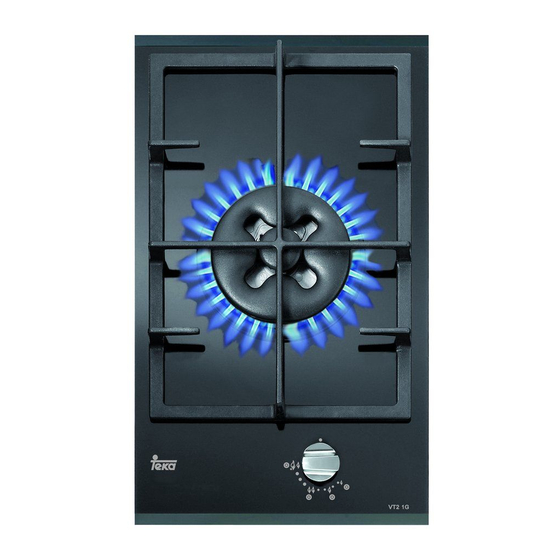
VT 2 1G AI AL TR CI E1
VT 2 2G AI AL CI E1
Instructions Manual
VT 2 1G AI AL TR CI E1
VT 2 2G AI AL CI E1
COD. 04075GGTKE1LPG (04075ING) - 26.07.2013
Advertisement

Subscribe to Our Youtube Channel
Related Manuals for Teka VT 2 1G AI AL TR CI E1


Summary of Contents for Teka VT 2 1G AI AL TR CI E1
- Page 1 Instructions for the installation and advice for the maintenance VT 2 1G AI AL TR CI E1 VT 2 2G AI AL CI E1 Instructions Manual VT 2 1G AI AL TR CI E1 VT 2 2G AI AL CI E1 These instructions are only valid if the country symbol appears on the appliance.
- Page 2 DESCRIPTION OF THE HOT PLATES MODELS: VT 2 1G AI AL TR CI E1 - VT 2 2G AI AL CI E1 1 “DUAL” burner 4200 W 2 Fast burner 2800 W 5 Auxiliary burner 1000 W 6 1F “DUAL” grill 7 2F grill 8 Burner no.1 control knob...
- Page 3 1) TRADITIONAL BURNERS until the indicator points to the maximum delivery position obtaining the maximum flow capacity of On the surface of the hob, there is a serigraphic both flames. figure above each knob, indicating the burner to When the flames are lit, keep the knob pressed for which the knob refers.
- Page 4 - The machine must not be used by people Power Ø Pan Burners (including children) with impaired mental or (cm) physical capacities, or without experience of 22 ÷ 27 using electrical devices, unless supervised or complete DUAL 4200 instructed by an expert adult responsible for central DUAL 8 ÷...
- Page 5 WARNINGS AND ADVICE FOR THE USER: - the use of a gas hob produces heat and humidity in the room where it is installed. Consequently, the room must be well aired, keeping natural ventilation openings free (fig. 3) and activating the mechanical aeration device (suction hood or electric fan fig.
- Page 6 CLEANING CAUTION: - Traces of liquid spilled from pans can be before cleaning the appliance, disconnect it eliminated with vinegar or lemon juice. from the gas and electricity supplies. - Never allow sugar or sugary foods to fall on the hob while cooking.
- Page 7 CLEANING The enamelled grids, enamelled covers “A”, “B” and - Do not use jets of steam to clean the “C”, and burner heads “M” (see fig. 7 and 7/A) must appliance. also be washed and the ignition elements “AC” and - To prevent difficulties with lighting, regularly safety cut-off sensors “TC”...
-
Page 8: Technical Information
INSTALLATION TECHNICAL INFORMATION Make a hole in the worktop to accommodate the hob, using the measurements indicated in fig. 9, FOR FITTERS ensuring that the critical dimensions of the space in Installation regulation, which the appliance must be installed are observed transformation and maintenance operations (see fig. - Page 9 INSTALLATION 4) FITTING THE HOB - Stick the seal to the glass evenly and securely, using your fingers to press it into place. The hob is equipped with a special seal to avoid - Position the hob in the hole in the unit and fasten it in any infiltration of liquid into the unit.
- Page 10 INSTALLATION I M P O RTA N T I N S TA L L AT I O N 6) LOCATION AND AERATION I N S T R U C T I O N S Gas cooking appliances must always dispose of their combustion fumes through hoods.
- Page 11 INSTALLATION 7) GAS CONNECTION GAS PRESSURE TEST Some hot plates models have a test point fitted Before connecting the appliance, check that the under the control panel, to conduct a gas pressure values on the data label affixed to the underside of the hot plate correspond to those of the gas test proceed as follows: mains in the home.
- Page 12 INSTALLATION 8) ELECTRICAL CONNECTION - insert an omnipolar switch between the appliance and the power network, in a size suited to the load of the appliance, with a minimum aperture IMPORTANT: the appliance must be between contacts of 3 mm. installed following the manufacturer's - Remember that the earth cable must not be instructions.
- Page 13 REGULATION Before performing any regulation, disconnect It is understood that the aforementioned the electricity supply to the appliance. regulation must only be carried out with burners After carrying out any regulation or pre- which use G20, while for burners which use G30 regulation operations, any seals must be or G31 the screw must be blocked completely.
- Page 14 TRANSFORMERS 10) REPLACING NOZZLES regulation organs and apply the label corresponding to the new gas regulation carried The burners can be adapted to suited different out on the appliance in place of that previously types of gas by fitting the nozzles that correspond to applied.
- Page 15 MAINTENANCE Before carrying out any maintenance, Greasing the valves (see fig. 19 - 20) disconnect the appliance from the gas and If the movement of a valve becomes stiff, grease it electricity supplies. immediately following the instructions below: - dismantle the body of the valve. 11) REPLACING COMPONENTS - Clean the cone and its housing with a rag soaked To replace the components housed inside the hob...
- Page 16 MAINTENANCE POWER CABLE TYPES AND SECTIONS CABLE TYPE OF HOB TYPE OF POWER MONOPHASE Gas hob H05 RR-F Section 3 x 0.75 mm CAUTION!!! When replacing the power cable, the fitter must keep the earth conductor “B” longer than the phase conductor (fig.
- Page 17 TECHNICAL DATA PRINTED ON THE LABEL 1 “DOMINO” BURNER 2 “DOMINO” BURNERS “DUAL” Category = II Category = II 2H3+ 2H3+ G 30 - Butane = 28 - 30 mbar G 30 - Butane = 28 - 30 mbar G 31 - Propane = 37 mbar G 31 - Propane = 37 mbar G 20 - Natural = 20 mbar G 20 - Natural = 20 mbar...
- Page 18 TECHNICAL DATA OF THE APPLIANCE GAS REGULATION TECHNICAL ASSISTANCE AND SPARES Before leaving the factory, this appliance was tested and regulated by specially qualified experts in order to guarantee the best operating results. The original spare parts can be found only in our Technical Assistance Centres and authorised shops. Every repair or regulation operation which should become subsequently necessary must be carried out with the utmost care and attention by qualified personnel.
Need help?
Do you have a question about the VT 2 1G AI AL TR CI E1 and is the answer not in the manual?
Questions and answers