Advertisement
Quick Links
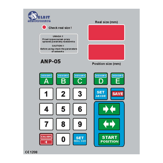
ANP-05
Automatic controller for two-sided cutting machine
Automatic cutting thickness regulating unit ANP-05 is designed for installation
in machines such as bilateral disc or belt trimming machines, or other machines
requiring manual or automatic setting of spacing of the vertically working saws.
Before assembly and start please read this handbook manual carefully,
instructions provided help you in correct mounting and operating of our product.
Advertisement

Related Manuals for Selbit ANP-05


Summary of Contents for Selbit ANP-05
- Page 1 ANP-05 Automatic controller for two-sided cutting machine Automatic cutting thickness regulating unit ANP-05 is designed for installation in machines such as bilateral disc or belt trimming machines, or other machines requiring manual or automatic setting of spacing of the vertically working saws.
- Page 2 CHAPTER 1 Mounting and controller’s connections During controller’s mounting is advised to follow this instructions correctly. Point - 1 Before mounting in the main board (fig. 1) please cut off rectangle hole 175 x 140 mm. This hole should be made carefully thus rubber sealing is adjoined to the from panel. Eventually any irregularity created after incorrect cutting out please smooth them using small metal file and protect it by anti-corrosion painting.
- Page 3 Figure 2. Mounted controller as separate device. In case of controller mounting as a separate device it is possible after its assembly to attached it to the machine’s frame using 4 added screws for this purpose. In another case please made special fixing for mounting the controller which can be used as a distance support as well (fig.
- Page 4 All cable connections should be made using special wires with double insulation oriented for use of the electric devices powered by 230V alternating current. Cables should be rounded with diameter suitable into holes in the controller back casing accordingly. Tips of the cables should be cleaned and special quill should be used or tips should be covered by thin tin layer.
- Page 5 Figure 3 Choke DPZ-320 constructions and connections Point – 4 Installation of the magnetic sensor In the machine where one head is mobile and aligned to the other stationary head linked mechanically to the machine body, the magnetic sensor should be mounted on a support connected to the stationary body.
- Page 6 from other cables. Please do not place any sources of the magnetic field next to the magnetic tape during, before and after mounting. It may cause it serious damage and incorrect working of the controller. Please clean the surface of the tape from time to time with sift brush. Please do not hit senor or the tape.
- Page 7 Point - 5 Connecting increase-reduce motion control cables Connect two pairs of wires to the head motion control contractors; short circuit (in the first or the second pair) will cause switching of the reduction contractor (the first pair) and of the increase contactor (the second pair).
-
Page 8: First Start
Controller’s connections checking To check the connections, follow these steps: - After turning on the power, check if the adjuster displays the message: “ANP-05”. Otherwise, check the TSS 8/001 transformer connections and retry. - After the message “ANP-05” disappears, press the green button with arrows pointing inwards;... - Page 9 Point 7 Checking the values of the input divider During the display of the “ANP-05” message, press and hold the “Calibr” button; after a while, the top display will show horizontal bars and the lower display will show the symbol of the divider (reversed T) and its current value.
- Page 10 To auto-calibrate, set the saws to the smallest dimension (smallest spacing of the saws), then switch on the control system, wait until the “ANP-05” message disappears from the display, then press and hold the “Calibr” button. The display will show the message: “Auto call”.
- Page 11 Controller ANP-05 is approved and fulfil all requirements concerning electromagnetic norms according to EMC. The controller ANP-05 should be set up and installed according to European and domestic norms. Responsible for adjusting the controller is person who set up the electric and control system on the sawing frame machine.
Need help?
Do you have a question about the ANP-05 and is the answer not in the manual?
Questions and answers