Advertisement
Quick Links
MANUAL HANDBOOK
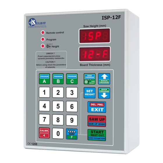
Automatic thickness controller for sawing frame machines
ISP – 12F
Automatic thickness controller ISP-12F is designed to be mounted on the sawing frame
machine.
Before assembly and start please read this handbook manual carefully, instructions
provided help you in correct mounting and operating of our product.
Advertisement

Related Manuals for Selbit ISP-12F


Summary of Contents for Selbit ISP-12F
- Page 1 MANUAL HANDBOOK Automatic thickness controller for sawing frame machines ISP – 12F Automatic thickness controller ISP-12F is designed to be mounted on the sawing frame machine. Before assembly and start please read this handbook manual carefully, instructions provided help you in correct mounting and operating of our product.
- Page 2 If on the main panel is no place to mount controller, it is possible to add it as separate device (fig. 2). Figure 1. Controller mounting on the main board. www.selbit.pl - 2 -...
- Page 3 Machine where the controller is mounted should be equipped in well working head saw ending switchers and contactors of the up and down feeding should be protected to be on at the same time !!! www.selbit.pl - 3 -...
- Page 4 Those CPZ outputs should connected in parallel to the contactors’ coil. CPZ should be connected with contactor’s coil of the down feeding, up feeding and barker contactor separately (if the sawing frame machine is equipped with barker). Fig. 3 Choke CPZ constructions and connections www.selbit.pl - 4 -...
- Page 5 Data from table 1 should be used during procedure of checking the controller’s parameters. Cable connection of the encoder should be routed as far as it is possible from other electrical cables. Using special clip bands lead it to the place where the controller is mounted. www.selbit.pl - 5 -...
- Page 6 “is above” the tape in all range. Please notice the stability of the tape and the sensor during normal operating. Fig. 5 Sensor and magnetic tape mounting example www.selbit.pl - 6 -...
- Page 7 Instead of electronic limit switches, you can also use good quality mechanical limit switches with NC terminals, connecting them to the adjuster as shown in Figure 8. www.selbit.pl - 7 -...
- Page 8 Electrical connections of external components to the adjuster. Before connecting the wires, it is absolutely necessary to turn off the power supply of the converter and the ISP-12F adjuster! Connection of control inputs of the frequency converter For connection, use an 8-core screened control cable with a cross-section adapted to the connection terminals.
- Page 9 Connector of the adjuster Connections of the frequency converter ISP-12F (PWR CONVERTER ATV 320 3*380V) +24 ------------------------------------------------------ +24 GND (-24V) ------------------------------------------- COM L6 ------------------------------------------------------- DI6 L5 ------------------------------------------------------- DI5 L4 ------------------------------------------------------- DI4 L3 ------------------------------------------------------- DI3 L2 ------------------------------------------------------- DI2 L1 ------------------------------------------------------- DI1...
- Page 10 Similarly, connect the limit switch restricting the upward movement, this time to the MPS-UP connector. Instead of electronic you can use electromechanical switches and connect them as shown in the figure. Figure 8 Wiring diagram for electromechanical limit switches www.selbit.pl - 10 -...
- Page 11 Figure 9 Wiring diagram for manual remote control buttons Figure 10 Block diagram for MSK 320 magnetic encoder www.selbit.pl - 11 -...
- Page 12 Figure 11 Block diagram for rotary encoder www.selbit.pl - 12 -...
- Page 13 In order to optimize the stopping time of the head, appropriate brake resistors should be used, matching the performance of the frequency converter. When determining ramp times, make sure that they are not too small in relation to the machine's inertia. www.selbit.pl - 13 -...
- Page 14 Optimal selection for the Converter deceleration ramp time (s) speed and inertia of the Attention! Define the ramp time after activating the machine adjuster Minimum speed (Hz) <= from the value set in Maximum speed (Hz) the function tFr www.selbit.pl - 14 -...
- Page 15 Terminal DI6 – limit switch down Terminal DI5 – limit switch up Triggering with a low logic state from limit switches Type of stop after a signal from limit switches (ramp) Type of stop (standard) nSTP Limit switch operation memory (off) www.selbit.pl - 15 -...
- Page 16 Impulse of the direction of rotation – no Brake release current (A) Time needed to mechanically release the brake (set a different value if 0.00 necessary [s]) Auto Brake frequency threshold 0.00 Mechanical brake engage time (set a different value if necessary [s]) www.selbit.pl - 16 -...
- Page 17 After changing the message to YES, press and hold the knob for > 2s until the dots on the display stops flashing If the converter is supplied with the ISP-12F adjuster, you can restore the initial configuration as described above by selecting the CFG1 name in the FCSI function.
- Page 18 After changing the message to YES, press and hold the knob for > 2s until the dots on the display stops flashing After correct configuration of the converter, check the operation of the ISP-12F adjuster Start-up of the ISP-12F adjuster To check the correctness of connections, follow the steps below: After switching on the power supply, check whether the message ISP 12F is displayed.
- Page 19 1. If the value is not correct, please type in required one and save it to the controller’s memory pressing “Start/Next Cut” button. Text “Save” should be shown. www.selbit.pl - 19 -...
- Page 20 Example: if you want to type 2 mm first press 2 button and then 0. On the screen 2.0 value will be displayed. After checking and eventually changing the value of the saw trace to save it to the controller’s memory pressing “Start/Next Cut” button. Text “Save” should be shown. www.selbit.pl - 20 -...
- Page 21 After completing the calibration movements, the adjuster will turn off the head drive and the display will show the “End Call” message, confirming the correct completion of auto- calibration. www.selbit.pl - 21 -...
- Page 22 5 – Adjusting the height of the saw lift for the return movement Saw Up. After pressing the “Saw Up” button, the ISP-12F adjuster lifts the saw over the cut material to allows it to return safely to the beginning of the processed material.
- Page 23 12 mm. - Change the mode using the arrow keys. - The parameter is saved after pressing “Start/Next Cut”. After the above operations have been carried out correctly, the adjuster is ready for use. www.selbit.pl - 23 -...
- Page 24 To storage often use cutting value in one of the button follow: reboot the controller while ISP-12F is displaying press one of the A, B, C button and there will be Abc text and dashes shown on the screen next, please press again one of the button where the value will be saved, name of the value...
- Page 25 Every cutting operation when the “Saw UP” button is pressed, the head saw is being raised up on the initial level. To erased this level please press shortly “Saw Height” button. www.selbit.pl - 25 -...
- Page 26 Next please press “Start/Next Cut” and controller sets up the saw on the first cut level and now the cutting process is starts in manual mode. www.selbit.pl - 26 -...
- Page 27 - 27 -...
- Page 28 (if it is required to use the settled backward saw height as it is in case manual program). If the tip dimension is not being used, please save the program without providing it. www.selbit.pl - 28 -...
- Page 29 - 29 -...
- Page 30 “Save Program” button. If all of the 60 position are not used, the controller automatically overwrite them with last provided position. Overwriting causes eventually fitting to bigger diameter of the log than predicted by the operator. www.selbit.pl - 30 -...
- Page 31 Height” displayed needs to be checked and compared with the real head saw position. In case of the any divergence it needs to be corrected according to the procedure shows in the point 4 of the chapter 3 “real saw height settings”. www.selbit.pl - 31 -...
- Page 32 EMC Approval Controller ISP-12F is approved and fulfil all requirements concerning electromagnetic norms according to EMC. The controller ISP-12F should be set up and installed according to European and domestic norms. Responsible for adjusting the controller is person who set up the electric and control system on the sawing frame machine.
- Page 33 Action as described above. 7 The movement has been stopped, the adjuster displays the message or Action: - Check whether the limit switch has been activated. - Check that there is no open circuit in the limit switch connections. www.selbit.pl - 33 -...
Need help?
Do you have a question about the ISP-12F and is the answer not in the manual?
Questions and answers