Table of Contents
Advertisement
Available languages
Available languages
Quick Links
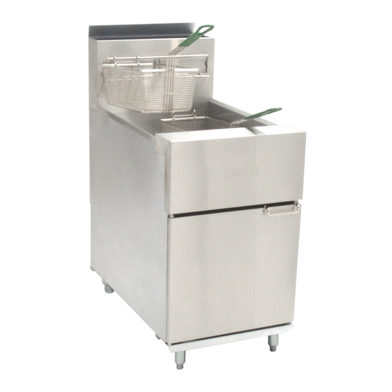
Dean Super Runner Series
SR52, SR62
Gas Fryers
Installation, Operation and Maintenance
Manual
This manual is updated as new information and models are released. Visit our website for the latest manual.
FOR YOUR SAFETY
Do Not Store or use gasoline
or other flammable vapors
and liquids in the vicinity of
this or any other appliance.
*8197501*
Part Number: FRY_IOM_8197501 02/2019
Original Instructions
READ THE INSTRUCTIONS BEFORE USING THE FRYER.
Keep these instructions for future reference.
Your Growth Is Our Goal
SR42,
CAUTION
Advertisement
Table of Contents

Subscribe to Our Youtube Channel
Related Manuals for Frymaster SR42 Series


Summary of Contents for Frymaster SR42 Series
- Page 1 Your Growth Is Our Goal Dean Super Runner Series SR42, SR52, SR62 Gas Fryers Installation, Operation and Maintenance Manual This manual is updated as new information and models are released. Visit our website for the latest manual. FOR YOUR SAFETY Do Not Store or use gasoline or other flammable vapors CAUTION...
-
Page 2: Notice To U.s. Customers
NOTICE IF, DURING THE WARRANTY PERIOD, THE CUSTOMER USES A PART FOR THIS FRYMASTER DEAN FOOD SERVICE EQUIPMENT OTHER THAN AN UNMODIFIED NEW OR RECYCLED PART PURCHASED DIRECTLY FROM FRYMASTER/DEAN, OR ANY OF ITS AUTHORIZED SERVICERS, AND/OR THE PART BEING USED IS MODIFIED FROM ITS ORIGINAL CONFIGURATION, THIS WARRANTY WILL BE VOID. - Page 3 Register Your Warranty Online at http://fm-hal.frymaster.com/qsys.lib/cgi.lib/swr290.pgm...
-
Page 4: Chapter 1: Installation Instructions
"A minimum distance of 18-inches (450-mm) should be maintained between the flue outlet and the lower edge of the grease filter". Frymaster recommends that the minimum distance be 24-inches (600-mm) from the flue outlet to the bottom edge of the filter. - Page 5 SUPER RUNNER SERIES GAS FRYERS CHAPTER 1: INSTALLATION INSTRUCTIONS For units equipped with legs: Lift the unit and move it into its final position. Do not drag or push the fryer into position. Doing so may damage the legs. Level the unit front to back and side to side. If the fryer is not level, the unit will not function efficiently.
- Page 6 SUPER RUNNER SERIES GAS FRYERS CHAPTER 1: INSTALLATION INSTRUCTIONS AUSTRALIAN REQUIREMENTS: To be installed on a firm, level surface in accordance with AS 5601 / AG 601, local authority, gas, electricity, and any other relevant statutory regulations. The Australian orifice size and manifold pressures are listed below for the SR42 and SR62 fryers.
- Page 7 SUPER RUNNER SERIES GAS FRYERS CHAPTER 1: INSTALLATION INSTRUCTIONS NOTE: If quick-disconnect supply lines or flex lines are used, increase supply line size to ¾-inch (22-mm) or larger. DANGER A manual shut-off valve must be installed in the gas supply (service) line upstream of this appliance and in a position where it can be reached quickly in the event of an emergency.
- Page 8 SUPER RUNNER SERIES GAS FRYERS CHAPTER 1: INSTALLATION INSTRUCTIONS ♦ After adjustment, replace the adjustment-screw cover. When converting from G20 (or G25) gas to G31 propane (or vice-versa), the following procedures apply: ♦ Burner orifices and pilot orifice MUST be replaced. Adjust orifice gas pressure to the appropriate value listed in the table on page 1-3 by turning the gas-valve ♦...
- Page 9 SUPER RUNNER SERIES GAS FRYERS CHAPTER 1: INSTALLATION INSTRUCTIONS Frypot Assembly 1/2—3/4 Reducer Manifold Support Bracket Bushing Gas Valve Gas Burner Burner See Detail A 1.63-inch [41-mm] Orifice 1.30-inch [33-mm] Pressure Test Gas Manifold Spigot Orifice Manifold Assembly Detail A Burner/Orifice Location Temperature Control...
- Page 10 SUPER RUNNER SERIES GAS FRYERS CHAPTER 1: INSTALLATION INSTRUCTIONS Series Runner Series Burner Orifice, 1.51mm (#53)- NON-CE ONLY: SR52 Burner Orifice, 2.53mm (#39)- NON-CE ONLY: SR52 & SR62 Series Only & SR62 Series Only Burner Orifice, 1.70mm (#51)- NON-CE ONLY: SR42 Burner Orifice, 2.80mm (#35)- NON-CE ONLY: S42 Series Only Series Only...
-
Page 11: Chapter 2: Operation
SUPER RUNNER SERIES GAS FRYERS CHAPTER 2: OPERATION 2.1 Initial Startup Wash the unit and accessories thoroughly with hot, soapy water to remove any film residue, dust or debris. Rinse and wipe dry. Close the drain valve completely. Ensure the operating thermostat and high-limit thermostat sensing bulbs inside the frypot are securely seated in the holding clamp. - Page 12 SUPER RUNNER SERIES GAS FRYERS CHAPTER 2: OPERATION 5. Fill the frypot with oil, shortening or water to the bottom OIL LEVEL line scribed on the frypot back. Ensure heating tubes are covered in liquid prior to engaging burners. NOTE: If solid shortening is used, pack the shortening into the frypot, ensuring the shortening is packed beneath, between and above the tubes prior to operating fryer.
- Page 13 SUPER RUNNER SERIES GAS FRYERS CHAPTER 2: OPERATION DANGER "Dry-firing" the fryer will cause damage to the frypot and can cause a fire. Always ensure that shortening, cooking oil or water covers the burner tubes before lighting the burners. 2. With the pilot lit, push down and slowly turn the gas valve knob to the ON position. 3.
-
Page 14: Wiring Diagram
SUPER RUNNER SERIES GAS FRYERS CHAPTER 2: OPERATION 2.5 Wiring Diagram CE UNITS ONLY: WARNING DO NOT CONNECT ANY EXTERNAL ELECTRICAL POWER TO THIS UNIT THERMOPILE HONEYWELL 807-3565 OPERATING THERMOSTAT COAXIAL LEAD TO THERMOCOUPLE 812-1284 HIGH-LIMIT HONEYWELL CE NON-CE UNITS ONLY: CONTROL CIRCUIT PILOT GENERATOR... - Page 15 Your Growth Is Our Goal Dean Serie Super Runner SR42, SR52, SR62 Freidoras A Gas Manual de instalación, operación y mantenimiento Este manual se actualiza en la medida en que surgen nuevos modelos e información. Visite nuestro sitio web para el manual más reciente. PARA SU SEGURIDAD No almacene ni use gasolina ni otros vapores o líquidos inflamables en la...
-
Page 16: Aviso A Los Clientes De Los Ee.uu
SI DURANTE EL PERÍODO DE GARANTIÁ, EL CLIENTE UTILIZA UNA PIEZA PARA ESTE EQUIPO ENODIS APARTE DE UNA PIEZA INALTERADA NUEVA O RECICLADA COMPRADA DIRECTAMENTE A FRYMASTER/DEAN, O ALGUNO DE SUS CENTROS DE SERVICIO AUTORIZADO, Y/O LA PIEZA QUE USE SE MODIFICA CON RESPECTO A SU CONFIGURACIÓN ORIGINAL, QUEDARÁ NULA ESTA GARANTÍA. - Page 17 Registre su garantía en línea en http://fm-hal.frymaster.com/qsys.lib/cgi.lib/swr290.pgm...
-
Page 18: Capítulo 1: Instrucciones De Instalación
“Debe mantenerse una distancia mínima de 450 mm (18 pulgadas) entre la salida del tiro y el borde inferior del filtro de grasa”. Frymaster recomienda que la distancia mínima sea 600 mm (24 pulgadas) desde la salida del tubo de tiro hasta el borde inferior del filtro. - Page 19 FREIDORAS DE GAS SERIE SUPER RUNNER CAPÍTULO 1: INSTRUCCIONES DE INSTALACIÓN unidad no funcionará en forma eficiente. Las freidoras de gas serie Super Runner no se pueden montar en un reborde y deben estar equipadas con las patas o ruedas que se incluyen. A.
- Page 20 FREIDORAS DE GAS SERIE SUPER RUNNER CAPÍTULO 1: INSTRUCCIONES DE INSTALACIÓN SOLAMENTE UNIDADES CE: En la tabla a continuación se indica la Entrada de calor nominal (Qn), tipo de gas, tamaño del orificio, presiones y ajustes, cantidad/color del orificio, marcas del quemador y marcas del piloto. ENTRADA DE TAMAÑO DEL PRESIÓN DE GAS EN EL REGULADOR CANTIDAD/...
- Page 21 FREIDORAS DE GAS SERIE SUPER RUNNER CAPÍTULO 1: INSTRUCCIONES DE INSTALACIÓN PELIGRO Debe instalarse una válvula de cierre manual en la línea de suministro de gas (servicio) antes de este aparato y en una posición donde ofrezca fácil acceso en caso de una emergencia. PELIGRO La freidora debe estar conectada al suministro de gas especificado en la placa de la capacidad nominal y número de serie ubicada en el interior de la puerta del aparato.
- Page 22 FREIDORAS DE GAS SERIE SUPER RUNNER CAPÍTULO 1: INSTRUCCIONES DE INSTALACIÓN Al convertir de gas G20 (o G25) a propano G31 (o viceversa), se aplican los siguientes procedimientos: DEBEN reemplazarse los orificios del quemador y del piloto. ♦ ♦ Ajuste la presión del gas del orificio al valor apropiado indicado en la tabla de la página 3-10 girando el tornillo de ajuste de la válvula de gas.
- Page 23 FREIDORAS DE GAS SERIE SUPER RUNNER CAPÍTULO 1: INSTRUCCIONES DE INSTALACIÓN Ensamblaje de la olla Buje Reucer de 1/2—3/4 Soporte del múltiple Quemador Válvula de gas de gas Quemador Ver detalle A 1.63-inch [41-mm] Orificio 1.30-inch [33-mm] Espita de Múltiple de gas prueba de Orificio presión...
- Page 24 FREIDORAS DE GAS SERIE SUPER RUNNER CAPÍTULO 1: INSTRUCCIONES DE INSTALACIÓN * Los orificios de quemadores indicados anteriormente son para las freidoras que funcionan a altitudes de 610 metros (2000 pies) o menos. Para altitudes mayores que 610 metros (2000 pies), comuníquese con la fábrica para conocer el tamaño correcto de orificio.
-
Page 25: Capítulo 2: Operación
FREIDORAS DE GAS SERIE SUPER RUNNER CAPÍTULO 2: OPERACIÓN 2.1 Arranque inicial Lave la unidad y los accesorios completamente con agua caliente y jabonosa para retirar toda película remanente de residuos, polvo o desechos. Enjuague y seque. Cierre completamente la válvula de drenaje. Asegúrese de que el termostato de operación y los bulbos sensores del termostato de límite alto dentro de la olla de la freidora estén correctamente ubicados en la abrazadera de soporte. - Page 26 FREIDORAS DE GAS SERIE SUPER RUNNER CAPÍTULO 2: OPERACIÓN Llene la olla con aceite o agua hasta la línea de NIVEL DE ACEITE del fondo ubicada en la parte posterior de la olla. Revise que los tubos calentadores estén cubiertos de líquido antes de encender los quemadores. Abra la válvula de cierre manual en la línea de suministro de gas entrante y gire la perilla de la válvula de gas a la posición PILOTO.
- Page 27 FREIDORAS DE GAS SERIE SUPER RUNNER CAPÍTULO 2: OPERACIÓN PELIGRO Si la freidora se “enciende en seco” ocasionará daños a la olla de la freidora y puede causar un incendio. Cerciórese siempre que la manteca vegetal, aceite para cocinar o agua cubra los tubos del quemador antes de encender los quemadores.
- Page 28 FREIDORAS DE GAS SERIE SUPER RUNNER CAPÍTULO 2: OPERACIÓN 2.5 Diagrama de cableado SOLAMENTE UNIDADES CE: ADVERTENCIA NO CONECTE NINGÚN SUMINISTRO ELÉCTRICO EXTERNO A ESTA UNIDAD. TERMOPILA HONEYWELL 807-3565 TERMOSTATO OPERATIVO CONDUCTOR COAXIAL A TERMOPAR 812-1284 LÍMITE ALTO HONEYWELL CE SOLAMENTE UNIDADES NO CE: CIRCUITO DE CONTROL GENERADOR...
-
Page 29: Pour Votre Sécurité
Your Growth Is Our Goal Dean Super Runner Series SR42, SR52, SR62 Friteuses à gaz Manuel d'installation, d'utilisation et d'entretien Ce manuel est mis à jour dès que de nouvelles informations et des modèles sont présentés. Visiter notre site Web pour les derniers manuels. POUR VOTRE SÉCURITÉ... -
Page 30: Avis Aux Clients Des États-Unis
L’installation, la maintenance et les réparations doivent être confiées à un centre de SAV agréé Frymaster ou à un autre professionnel qualifié. Toute installation, maintenance ou réparation effectuée par un personnel non qualifié risque d’annuler la garantie du fabricant. - Page 31 Enregistrez votre garantie en ligne à http://fm-hal.frymaster.com/qsys.lib/cgi.lib/swr290.pgm...
-
Page 32: Chapitre 1 : Instructions D'installation
NFPA No. 96 indique que « une distance minimum de 18 pouces (450 mm) doit être maintenue entre la sortie du conduit de fumée et le bord inférieur du filtre à graisse. » Frymaster recommande une distance minimum de 600 mm entre la sortie du conduit de fumée et le bord inférieur du filtre. - Page 33 FRITEUSES À GAZ SUPER RUNNER CHAPITRE 1 : INSTRUCTIONS D’INSTALLATION Pour les friteuses équipées de pieds : Soulevez la friteuse et amenez-la à sa position finale. Ne traînez pas la friteuse et ne la poussez pas jusqu’à sa position finale sous peine d’en endommager les pieds. Calez la friteuse en la mettant à niveau d’avant en arrière et d’un côté...
- Page 34 FRITEUSES À GAZ SUPER RUNNER CHAPITRE 1 : INSTRUCTIONS D’INSTALLATION MODÈLES CE UNIQUEMENT : L’apport de chaleur nominal (Qn), le type de gaz, la taille de l’orifice, les pressions et réglages, la quantité/couleur des orifices, les marquages des brûleurs et des veilleuses sont répertoriés ci-dessous : PRESSION DE GAZ AU APPORT DE RÉGULATEUR...
- Page 35 FRITEUSES À GAZ SUPER RUNNER CHAPITRE 1 : INSTRUCTIONS D’INSTALLATION DANGER Un robinet d’arrêt manuel doit être installé sur la conduite d’arrivée de gaz (réseau) de cet appareil et à un endroit facilement accessible en cas d’urgence. DANGER La friteuse doit être connectée au réseau de gaz spécifié sur la plaque signalétique derrière la porte de la friteuse.
- Page 36 FRITEUSES À GAZ SUPER RUNNER CHAPITRE 1 : INSTRUCTIONS D’INSTALLATION Lors de la conversion du gaz G20 (ou G25) à du propane G31 (ou vice versa), les procédures suivantes s’appliquent : Les orifices du brûleur et l’orifice de la veilleuse DOIVENT être remplacés. ♦...
- Page 37 FRITEUSES À GAZ SUPER RUNNER CHAPITRE 1 : INSTRUCTIONS D’INSTALLATION Bassin de friture Patte de fixation Toile d'émeri ½ - ¾ de la rampe Robinet de gaz Brûleur à gaz Brûleur Voir détail A 41-mm Orifice 33 mm Rampe des Robinet brûleurs à...
- Page 38 FRITEUSES À GAZ SUPER RUNNER CHAPITRE 1 : INSTRUCTIONS D’INSTALLATION Plaque signalétique, contactez l’usine au moment de la Plaque signalétique contactez l’usine au moment de la conversion. conversion. * Les orifices de brûleur indiqués ci-dessus sont destinés aux friteuses fonctionnant à 610 mètres d’altitude maximum. Pour les altitudes supérieures à...
- Page 39 FRITEUSES À GAZ SUPER RUNNER CHAPITRE 2 : MODE D’EMPLOI 2.1 Mise en marche initiale Lavez minutieusement la friteuse et ses accessoires avec de l’eau savonneuse chaude pour retirer les résidus de film, les poussières et autres particules. Rincez et essuyez. Fermez à fond la vanne de vidange. Assurez-vous que les bulbes thermostatiques du thermostat de régulation et du thermostat de protection surchauffe à...
- Page 40 FRITEUSES À GAZ SUPER RUNNER CHAPITRE 2 : MODE D’EMPLOI Remplissez d’huile la cuve jusqu’au repère OIL LEVEL inférieur, à l’arrière de la cuve. Assurez-vous que les tubes chauffants sont recouverts de liquide avant d’allumer les brûleurs. Ouvrez le robinet d’arrêt manuel de la conduite d’arrivée de gaz (réseau) et tournez le bouton du robinet de gaz à la position PILOT.
- Page 41 FRITEUSES À GAZ SUPER RUNNER CHAPITRE 2 : MODE D’EMPLOI DANGER L’allumage à vide de la friteuse endommagera la cuve et risquera de causer un incendie. Assurez-vous toujours que de la graisse, de l’huile de cuisson ou de l’eau recouvre les tubes des brûleurs avant d’allumer ces derniers.
- Page 42 FRITEUSES À GAZ SUPER RUNNER CHAPITRE 2 : MODE D’EMPLOI 2.5 Diagramme de câblage MODÈLES CE UNIQUEMENT : AVERTISSEMENT NE PAS CONNECTER TOUTE ALIMENTATION ÉLECTRIQUE EXTERNE À CETTE UNITÉ PILE THERMOÉLECTRIQUE HONEYWELL 807-3565 L'UTILISATION THERMOSTAT LIGNE COAXIALE AU THERMOCOUPLE 812-1284 PROTECTION DE SURCHAUFFE HONEYWELL CE MODÈLES NON-CE UNIQUEMENT :...
- Page 43 THIS PAGE INTENTIONALLY LEFT BLANK...
- Page 44 FRYMASTER 8700 LINE AVENUE, SHREVEPORT, LA 71106-6800 800-551-8633 318-865-1711 WWW.FRYMASTER.COM EMAIL: FRYSERVICE@WELBILT.COM Manufactured at Manitowoc (China) Foodservice Co., Ltd 151 Jianye Road Binjian District Hangzhou, Zhenjiang, 310052 China *8197423* WWW.WELBILT.COM Welbilt provides the world’s top chefs, and premier chain operators or growing independents with industry leading equipment and solutions.
Need help?
Do you have a question about the SR42 Series and is the answer not in the manual?
Questions and answers